Warning
You are reading an old version of this documentation. If you want up-to-date information, please have a look at 5.4 .What performs vision calibration?
What are the corrections made with the checkerboard?
Correct image distortion: Once the calibration is done, each time an image is acquired, the distortion will be automatically corrected.
Note
For more information about what distortion is and how it is corrected, refer to the section Distortion correction.
Define the region of interest (ROI): The ROI is the residual region of the images that will be used later for any image analysis. It is a way to reject image regions that are not used for image analysis:
The left and right sides of the images always include regions outside the Asycube.
If in your integration, the same part of the image is always hidden by another device (hopper, robot, lights, …), this part will be automatically rejected from the ROI.
Important
For this reason, make sure you have the same system integration that you will have during production to ensure rejection of undesired regions of the image.
Do not disassemble your hopper, robot, lights (etc…) to get a better calibration result! This may cause image analysis errors when editing recipes or during production.
In Fig. 165, the ROI is the green rectangle surrounding the checkerboard.
Determine the pixel-millimeter or pixel-inch scale: The origin and orientation of the vision system coordinate does not change (Fig. 255). The system coordinate before vision calibration goes from 0 to 3072px in x and from 0 to 2048px in y. The system coordinate after vision calibration goes from 0 to the image width in millimeters/inches and from 0 to the image height in millimeters/inches (Table 34).
Table 34 Vision change of coordinate Before calibration
After calibration
Reference
X
Y
X
Y
Point 1
0
0
0
0
Point 2
3072px
0
Width
0
Point 3
0
2048px
0
Height
Point 4
3072px
2048px
Width
Height
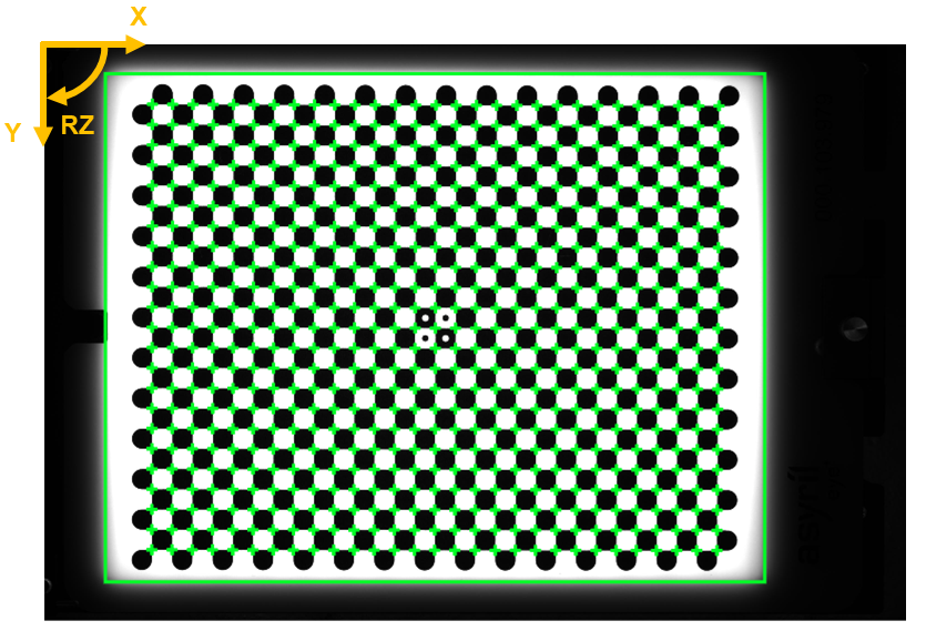
Fig. 255 Vision system coordinate
Distortion correction
The main goal of the vision calibration is the distortion correction.
Distortion is a monochromatic optical aberration that results in a variation of magnification in the image for a fixed working distance. A checkerboard image subjected to distortion will produce curved lines instead of straight lines (left checkerboard from Fig. 256).
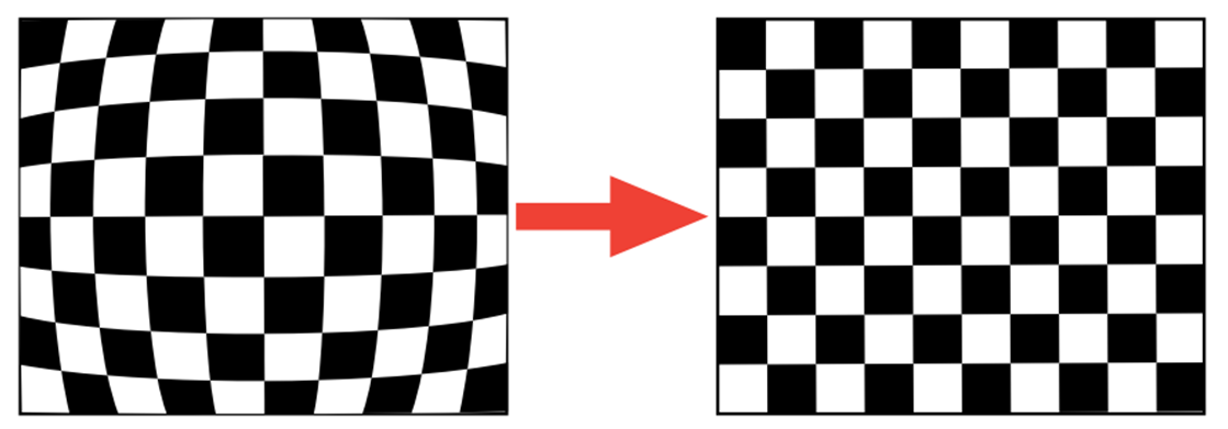
Fig. 256 Optical distortion correction (left: before calibration, right: after calibration)
Distortion does not technically reduce the information contained in the image, as it only displaces the information geometrically. This means that the distortion can be effectively calculated from an image and therefore corrected without losing much information.
A distortion model is determined by looking for the distortion parameters and the parameters of the intrinsic and extrinsic properties of a camera to fit the checkerboard lines of the distorted image. The model attempts to reconstruct the curved lines. Once these parameters are found, the distortion correction transformation can be applied to the distorted image.
Note
The distortion correction transform is a mathematical operation, based on the distortion parameters, applied to the image. It will be applied to each image acquired, before performing any image analysis.
The Fig. 165 shows an image of the checkerboard before (left) and after (right) the distortion correction. The detected checkerboard corners are represented by green crosses.
RMS error
In the step 9. Camera configuration results, we provide you with the root mean square error (RMS) of the distortion reconstruction. This is the average error between the expected checkerboard and the checkerboard resulting from the distortion reconstruction. The closer the re-projection error is to zero, the more accurate the parameters we have found.
Important
If the RMS error is greater than 1, the correction is not applicable.
Note
The checkerboard is also used to determine the pixel-millimeter or pixel-inch scale presented in result step 9.
Perspective projection correction
By providing the height of the camera in step 7 (the working distance), the system will be able to correct the effects of perspective projection.
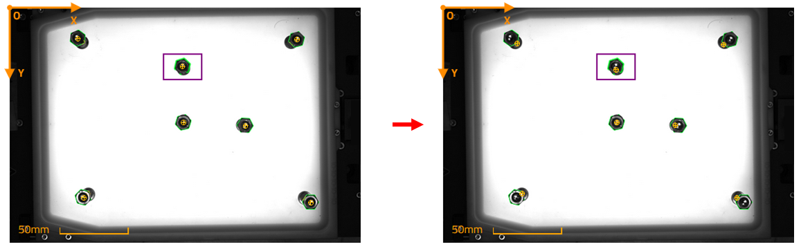
Fig. 257 Left: Before perspective correction; Right: After perspective correction; Pick point described by the yellow target
Perspective projection is the mathematical rule which defines how a 3D scene is mapped onto a 2D image. Since the camera cannot be orthogonal (i.e. all light rays hitting the sensor perpendicularly), this projection introduces a geometrical shift between the top and bottom surfaces of the parts where the top will look farther away from the center than the bottom. That effect is more pronounced the farther away the parts are from the center of the Asycube and the taller they are (taller = more error). This phenomenon causes a shift in the picking coordinates and a loss of precision.
In the situation presented in Fig. 258, the perspective projection error produces a displacement to the right of the upper surface of the cylinder with respect to the base of the cylinder (right cylinder) from the camera’s point of view. The variation in Y caused is the distance e between the yellow point (real position) and the red point (position detected by EYE+: this position is shifted due to perspective). The yellow point is the corrected position of cylinder center projected on the camera plane (horizontal black dashed line).
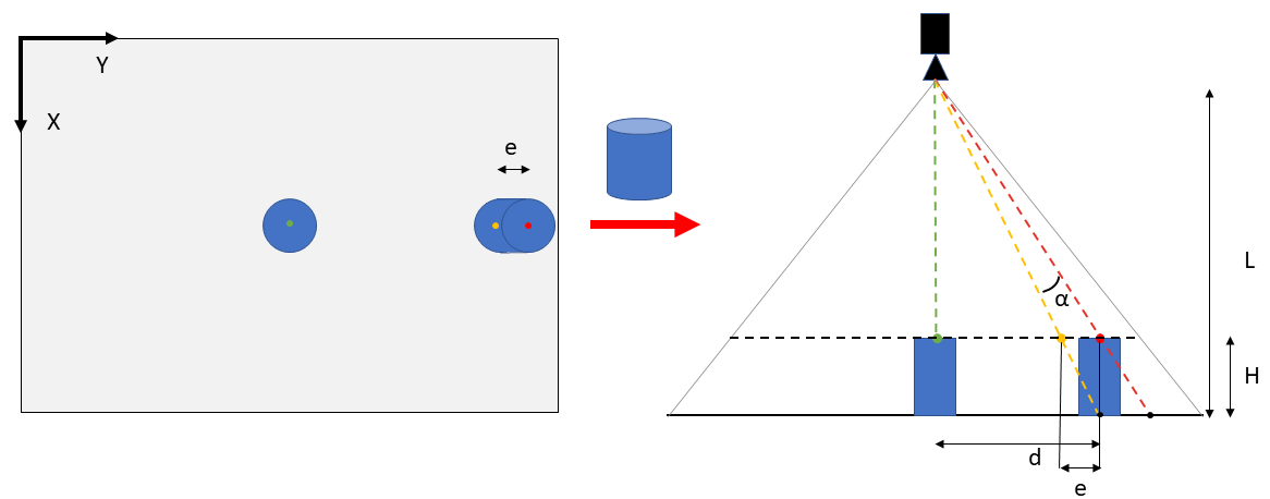
Fig. 258 Perspective correction of a cylinder (left: top view, right: side view). Yellow point: real picking position; Red point: position detected by EYE+ without perspective correction.
Tip
Try to imagine the resized image of the lower plane (horizontal black line) projected on the camera plane (dashed black line). The image is resized by R to remain in the vision cone.
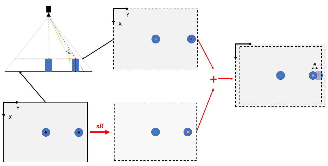
Fig. 259 Lower plan (horizontal black line) projection on camera plane (horizontal black dashed line) view from the top. The projection is resized by ration of R.
EYE+ corrects the perspective projection effect by adding an offset on the X and Y coordinates of the part according to its position on the Asycube plate. A part located on the edge of the plate will have a greater offset than a part located in the center. To calculate these offsets, the system needs to know the height of the part and the distance from the camera to the Asycube plate.
Note
The perspective projection correction is not performed when configuring the camera but later, when you provide the height of the part to the system for the calculation of the coordinates.