Warning
You are reading an old version of this documentation. If you want up-to-date information, please have a look at 5.4 .Module overview
The EtherCAT Module is schematically equivalent to:
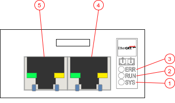
Fig. 218 EtherCAT Module
System LED (SYS)
Run LED (RUN)
Error LED (ERR)
Interface X1 (EtherCAT IN), standard RJ45
Interface X2 (EtherCAT OUT), standard RJ45
LEDs Behavior
The subsequent table describes the meaning of the various LEDs found on the device.
LED |
Color |
State |
Description |
|---|---|---|---|
RUN |
Off |
Off |
Module in state INIT |
Green |
Blinking |
Module in state PRE-OPERATIONAL |
|
Green |
Single Flash |
Module in state SAFE-OPERATIONAL |
|
Green |
Solid |
Module in state OPERATIONAL |
|
ERR |
Off |
Off |
No error |
Red |
Blinking |
Internal Error |
|
Red |
Single |
Internal Error |
|
Red |
Solid |
Internal Error |
|
Ethernet LED |
Off |
Off |
No link established |
Green |
Blinking |
Module is transmitting |
|
Green |
Solid |
A link is established |
Network topology
When multiple EtherCAT devices are to be connected, two topologies can be implemented:
- Daisy chain and/or star topology:
Modules are connected like a daisy chain where Module 1 EtherCAT Output is connected to Module 2 EtherCAT Input, and so on. The last module does not require to be connected back to the master.
- Ring topology:
Modules are connected such that they form a ring, Module 1 EtherCAT Output is connected to Module 2 EtherCAT Input, and so on. The last module is connected back to the EtherCAT Master, thus forming a ring.
Please, review your requirements to choose which topology best fits your needs.
Process Data Objects
EtherCAT allows exchanging cyclic real-time data using Process Data Objects (PDOs). There are two types of PDOs corresponding to the two directions: RxPDOs and TxPDOs.
All the necessary commands, parameters and output data are implemented in PDOs so that you can easily and fully integrate your EYE+ into your application. PDOs are mostly mirroring the TCP Protocol interface while providing a specific and convenient interface to use. We highly recommend you read the TCP programming guide before integrating EYE+ using the EtherCAT Module.
The ESI file can be directly downloaded from EtherCAT Downloads.
RxPDO
Name |
Data Type |
|---|---|
UDINT |
|
BOOL |
|
BOOL |
|
Recipe ID |
UDINT |
BOOL |
|
BOOL |
|
BOOL |
|
BOOL |
|
BOOL |
|
BOOL |
|
BOOL |
|
REAL |
|
USINT |
|
USINT |
|
USINT |
|
USINT |
|
USINT |
|
BOOL |
|
BOOL |
|
BOOL |
|
UDINT |
|
BOOL |
|
BOOL |
|
BOOL |
|
BOOL |
|
BOOL |
|
BOOL |
|
BOOL |
|
USINT |
|
REAL |
|
REAL |
|
USINT |
|
USINT |
|
USINT |
|
USINT |
|
USINT |
|
USINT |
TxPDO
Name |
Data Type |
|---|---|
UDINT |
|
BOOL |
|
BOOL |
|
UDINT |
|
BOOL |
|
BOOL |
|
UDINT |
|
BOOL |
|
BOOL |
|
BOOL |
|
BOOL |
|
BOOL |
|
USINT |
|
USINT |
|
USINT |
|
USINT |
|
USINT |
|
USINT |
|
Repetition of 10 poses (N = 1 to 10) |
|
REAL |
|
REAL |
|
REAL |
|
USINT |
|
BOOL |
|
BOOL |
|
BOOL |
|
REAL |
|
USINT |
|
USINT |
|
USINT |
|
USINT |
|
USINT |
|
BOOL |
|
BOOL |
|
BOOL |
|
BOOL |
|
BOOL |
|
BOOL |
|
BOOL |
|
BOOL |
|
BOOL |
|
BOOL |
|
REAL |
|
Repetition of 6 model prepared (N = 1 to 6) |
|
USINT |
|
Repetition of 6 model quantity read-back (N = 1 to 6) |
|
USINT |
|
Repetition of 10 poses model (N = 1 to 10) |
|
USINT |
|