Warning
You are reading an old version of this documentation. If you want up-to-date information, please have a look at 5.4 .EYE+ Controller
Dimensions
The EYE+ Controller can be fixed using the two brackets. All the dimensions required to mount the EYE+ Controller in your electrical cabinet are presented in Fig. 13.
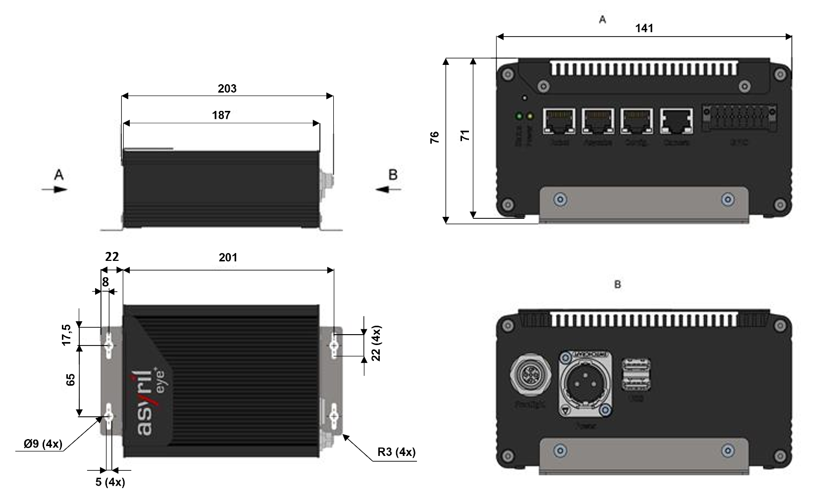
Fig. 13 Dimensions of EYE+ Controller and mounting brackets
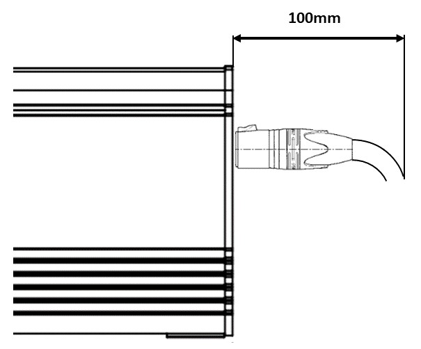
Fig. 14 Dimensions of EYE+ Controller power connector + cable folding (CC)
Characteristic |
Value |
|---|---|
Weight |
1.26kg |
Dimensions |
187 x 141 x 71 mm |
Storage Temperature |
+5°C to 40°C |
Operating Temperature |
+5°C to 40°C |
Humidity |
Operating: 30% to 85% |
Ingress Protection |
IP30 |
Mounting the EYE+ Controller
Unpack the EYE+ Controller.
Fix the EYE+ Controller inside your electrical cabinet using four M4 screws. We advice you to fix the EYE+ Controller vertically and to ventilate the cabinet. Refer to EYE+ Controller standard specifications section for more details.
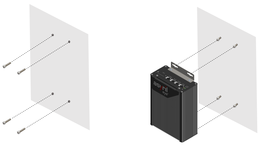
Fig. 15 EYE+ Controller mounting step 1 and 2
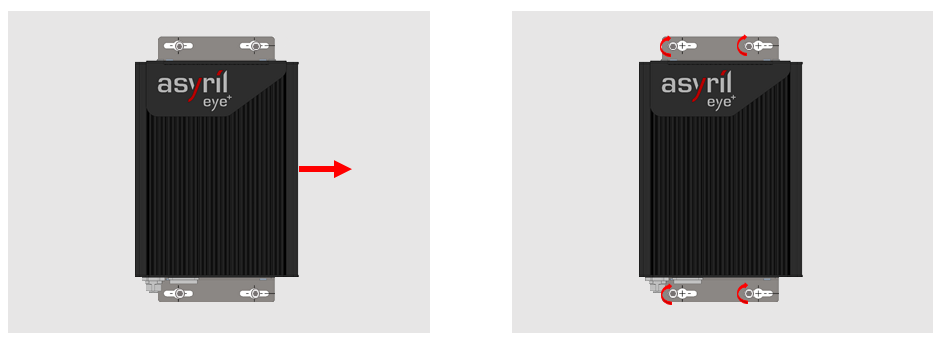
Fig. 16 EYE+ Controller mounting step 3 and 4