Warning
You are reading an old version of this documentation. If you want up-to-date information, please have a look at 5.4 .5.3 Results
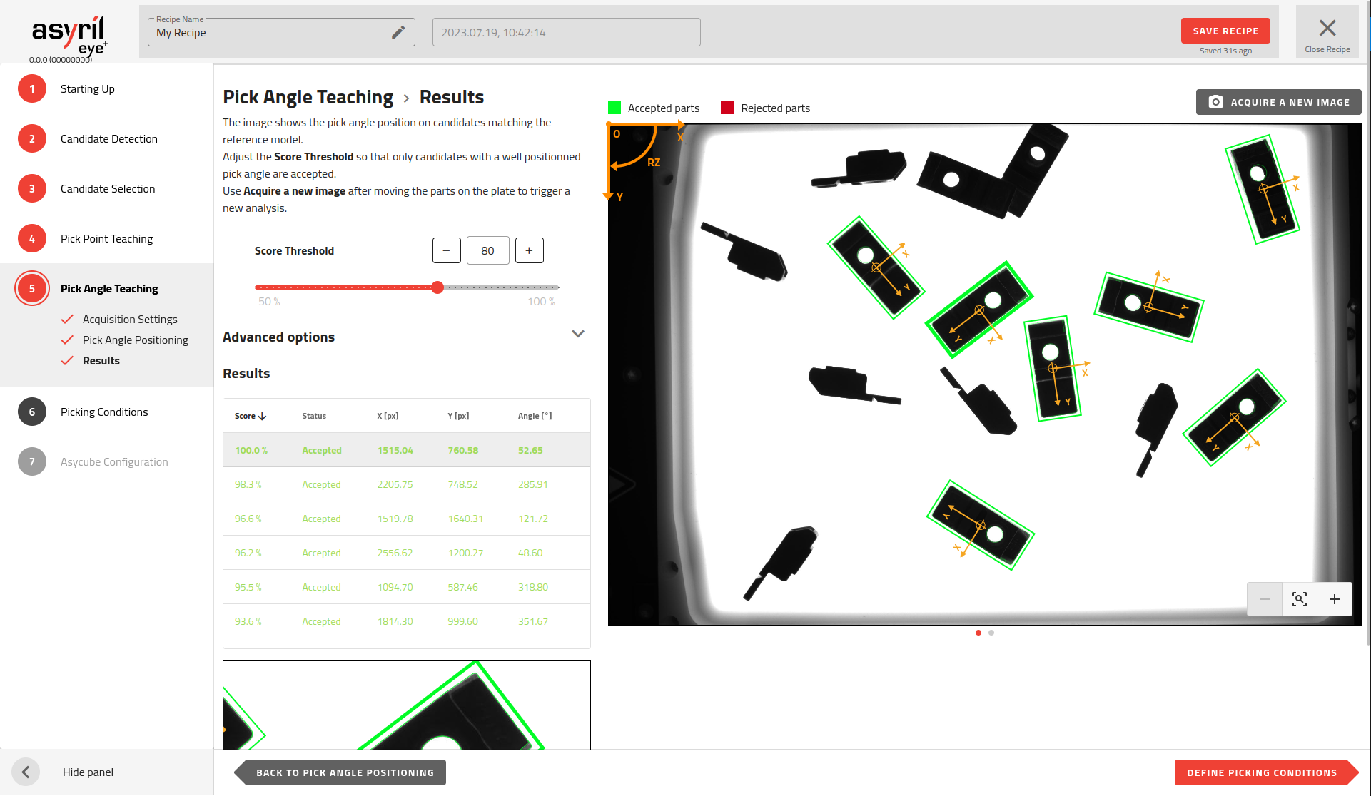
Fig. 108 Pick Angle Teaching - Results
The reference model, resulting from the pick point position and residual features, is then compared with the features of all other good candidates. The reference model is rotated until the features of the reference model match the features detected on the other candidates as closely as possible.
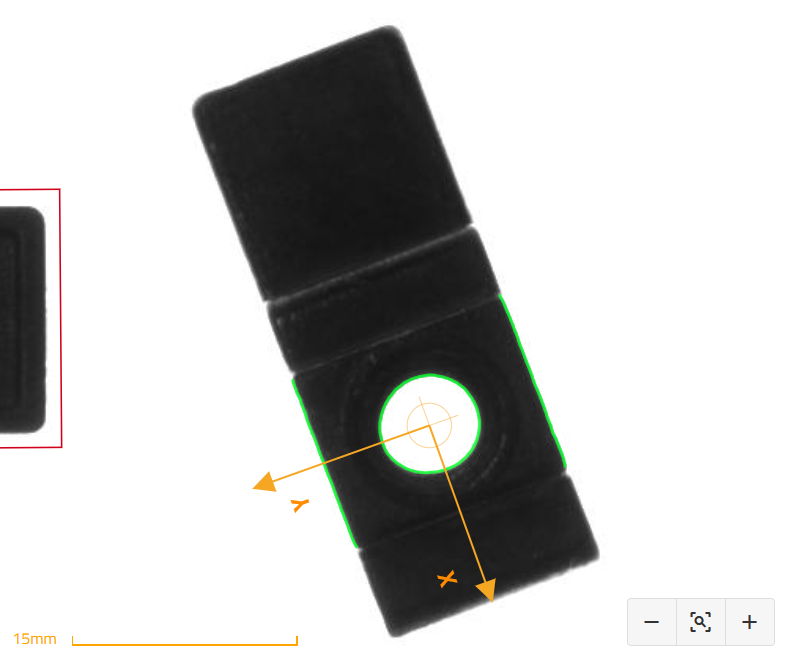
Fig. 109 Pick angle teaching result - zoomed in on one part
Tip
You can manually move the parts on the feeder and then hit the “acquire a new image” button to check if the pick angle is always well detected.
The score represents the matching percentage between the reference model and the candidate. A score of 100% means a perfect match.
Tip
In the results table, you can sort the parts in ascending order of score and thus easily verify that all parts with a score higher than the threshold are precisely detected (i.e. accurate pick angle positioning) . Adjust the threshold to keep only accurately detected parts as accepted (surrounded by a green rectangle).
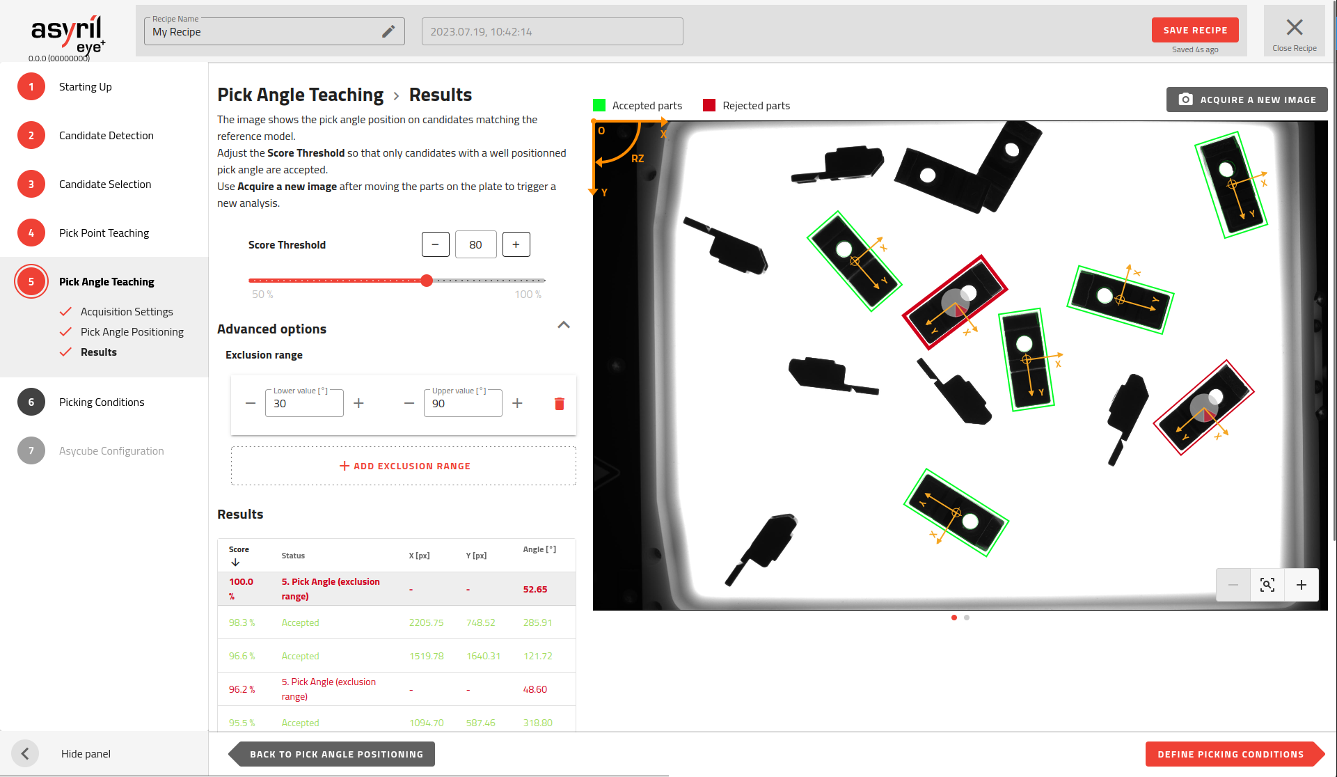
Advanced options
The advanced options provide an additional setting to add up to four angular exclusion ranges.
Note
An exclusion range comprises a pair of angles. When a part’s angle falls within this range, the part is deemed “rejected.”
A range can be set with values from -360° to 360°. However, the vision system goes from 0° to 360°. For this reason, if an angle is entered as a negative value, once you save the exclusion range, a transposition to the corresponding positive value will occur by adding 360. For example, an exclusion range “[-30; 30]” is saved as “[330; 30]”.
Advanced options can be displayed by clicking on the top right of the title.
Important
In the recipe wizard, the angles are expressed in the vision reference frame as defined by the coordinate system on the top left of the image. In production however, EYE+ will return the angles in the robot frame, as calculated by the hand-eye calibration.