Warning
You are reading an old version of this documentation. If you want up-to-date information, please have a look at 5.3 .2. Candidate Detection

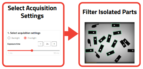
Fig. 53 Candidate Detection overview
The purpose of Candidate Detection is to detect candidates (i.e. potential good parts that are “candidates” for the next steps of the wizard) according to their size. The EYE+ detection algorithm filters out elements that are too small or too large in the image. Undesirables include:
several parts in contact detected as one
platform debris
shapes or shadows of the production plate (e.g. production plate with grooves)
Tip
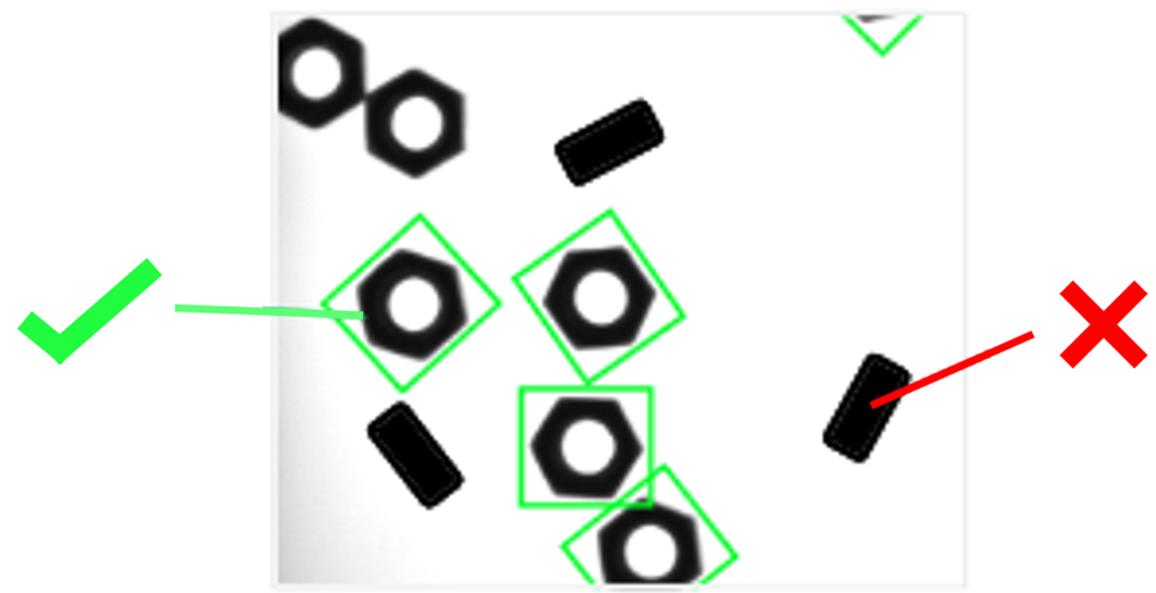
The candidate detection can even filter a part that has a wrong face up if the size of said face is different from that of the desired one.

Fig. 54 The orientation of the parts is filtered by their size. Parts that are in the wrong orientation in this case are smaller in area, and are therefore filtered out.
At the end of this step, you should have as many isolated parts as possible surrounded by a green rectangle (called a bounding box) and as few of the wrong size elements detected as possible (dust, background element …).
Segmentation image
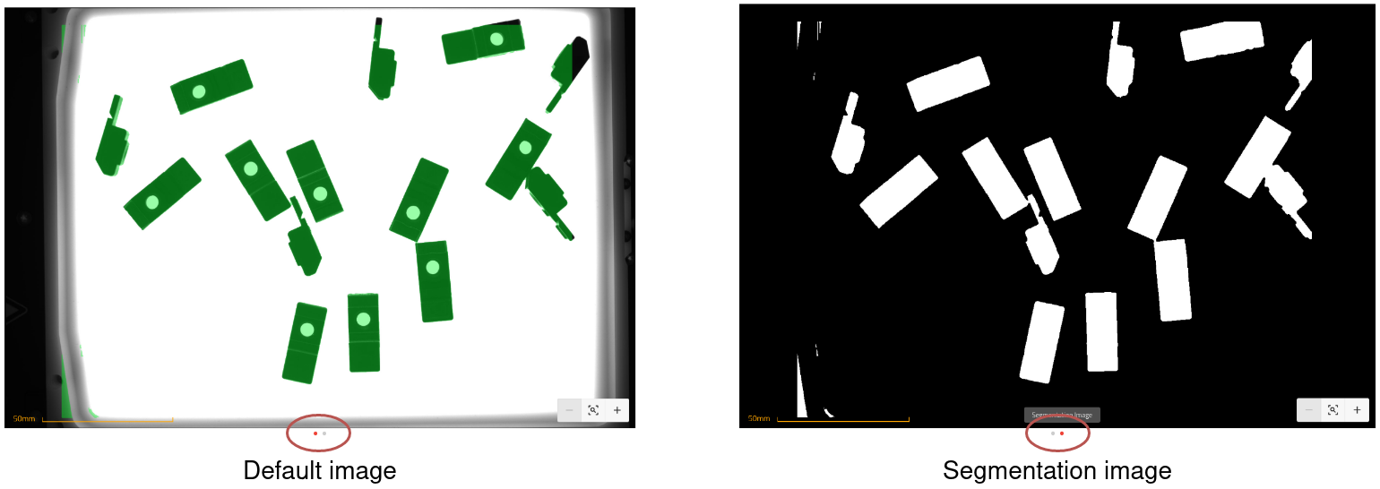
All the settings you set at this step will be used to generate a black and white image with only the candidates in white that’s called a segmentation image. This helps the system process input data faster. To see the resulting segmentation image, you may click on the dots under the default image to switch between it and the segmentation image.
This can help you decide whether you need to use a custom region of interest (see next page for more details).

Fig. 55 Changing between default and segmentation images