Warning
You are reading an old version of this documentation. If you want up-to-date information, please have a look at 5.4 .Module overview
The PROFINET IO Module is schematically equivalent to:
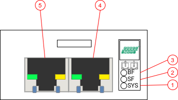
Fig. 233 PROFINET IO Module
System LED (SYS)
System Failure LED (SF)
Bus Failure LED (BF)
Interface X1, standard RJ45
Interface X2, standard RJ45
LEDs Behavior
The subsequent table describes the meaning of the various LEDs found on the device.
LED |
Color |
State |
Description |
|---|---|---|---|
SF |
Off |
Off |
No error |
Red |
Flashing |
DCP signal service is initiated via the bus |
|
Red |
On |
Generic or extended diagnosis present; System error |
|
BF |
Off |
Off |
No error |
Red |
Flashing |
No data exchange |
|
Red |
On |
No configuration or No physical link |
|
Ethernet LED |
Off |
Off |
No link established |
Green |
Blinking |
Module is transmitting |
|
Green |
Solid |
A link is established |
Network topology
When multiple PROFINET IO devices are to be connected, three topologies can be implemented:
- Daisy chain and/or star topology:
Modules are connected like a daisy chain where Module 1 is connected to Module 2, and so on. The last module does not require to be connected back to the master.
- Ring topology:
Modules are connected such that they form a ring, Module 1 is connected to Module 2, and so on. The last module is connected back to the PROFINET IO Scanner, thus forming a ring. The module can act as a MRP Client as per specification.
- Tree topology:
Modules are connected such that they form a tree. A Module is the root node to which multiple Modules (branches) can be connected. The last modules (at the end of the branches) do not require to be connected back to the master.
Please, review your requirements to choose which topology best fits your needs.
Inputs / Outputs
PROFINET IO allows exchanging cyclic real-time data using Inputs / Outputs.
All the necessary commands, parameters and output data are implemented in Inputs / Outputs so that you can easily and fully integrate your EYE+ into your application. Assemblies are mostly mirroring the TCP Protocol interface while providing a specific and convenient interface to use. We highly recommend you read the TCP programming guide before integrating EYE+ using the PROFINET IO Module.
The GSDML file can be directly downloaded from PROFINET IO Downloads.
Inputs
Name |
Data Type |
|---|---|
UDINT |
|
BOOL |
|
BOOL |
|
Recipe ID |
UDINT |
BOOL |
|
BOOL |
|
BOOL |
|
BOOL |
|
BOOL |
|
BOOL |
|
BOOL |
|
REAL |
|
USINT |
|
USINT |
|
USINT |
|
USINT |
|
USINT |
|
BOOL |
|
BOOL |
|
BOOL |
|
UDINT |
|
BOOL |
|
BOOL |
|
BOOL |
|
BOOL |
|
BOOL |
|
BOOL |
|
BOOL |
|
USINT |
|
REAL |
|
REAL |
|
USINT |
|
USINT |
|
USINT |
|
USINT |
|
USINT |
|
USINT |
Outputs
Name |
Data Type |
|---|---|
UDINT |
|
BOOL |
|
BOOL |
|
UDINT |
|
BOOL |
|
BOOL |
|
UDINT |
|
BOOL |
|
BOOL |
|
BOOL |
|
BOOL |
|
BOOL |
|
USINT |
|
USINT |
|
USINT |
|
USINT |
|
USINT |
|
Number of Valid Entries |
USINT |
Repetition of 10 poses (N = 1 to 10) |
|
REAL |
|
REAL |
|
REAL |
|
USINT |
|
BOOL |
|
BOOL |
|
BOOL |
|
REAL |
|
USINT |
|
USINT |
|
USINT |
|
USINT |
|
USINT |
|
BOOL |
|
BOOL |
|
BOOL |
|
BOOL |
|
BOOL |
|
BOOL |
|
BOOL |
|
BOOL |
|
BOOL |
|
BOOL |
|
REAL |
|
Repetition of 6 model prepared (N = 1 to 6) |
|
USINT |
|
Repetition of 6 model quantity read-back (N = 1 to 6) |
|
USINT |
|
Repetition of 10 poses model (N = 1 to 10) |
|
USINT |
|