Warning
You are reading an old version of this documentation. If you want up-to-date information, please have a look at 5.4 .Camera configuration wizard
This wizard guides you to finalize the vision system installation and to perform the vision calibration.
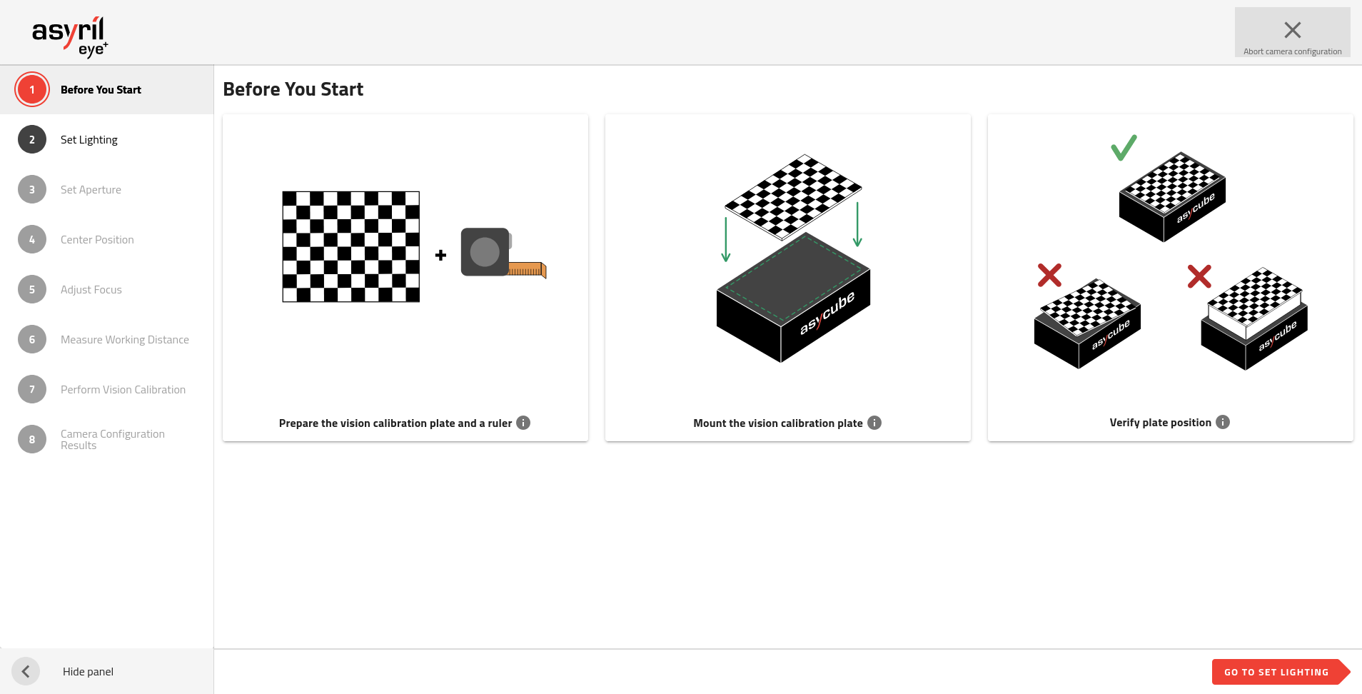
Fig. 145 Camera configuration wizard
The camera configuration wizard consists of 9 steps.
Before starting this wizard, ensure the camera is correctly installed:
Camera is placed above the center of the Asycube plate.
Distance between the front face of the lens and the Asycube plate corresponds to your EYE+ kit working distance (see Table 7).
The camera EYE+ logo is oriented opposite to the Asycube connectors (Fig. 20).
The lens cover is removed.
Note
Refer to section Mounting the camera and the lens to get more information.
1. Before you start
You must remove the production plate from the Asycube and mount the vision calibration plate on it. Refer to section Mounting vision calibration plate to mount it properly. The vision calibration plate must be rigidly fixed to the Asycube.
Prepare a ruler (in meters or inches).
Important
Keep the same installation it would be in production state. For example if in production state something obstructs the view of the camera on the side of the Asycube (for example a hopper), you must leave this element as it will allow to define the region of interest in your installation during the camera configuration.
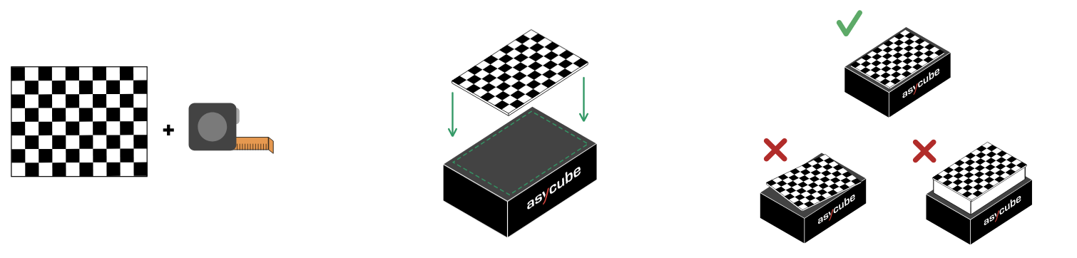
Fig. 146 Before you start
2. Set lighting
The system informs you if an Asycube is connected and what is the color of its backlight.
You have to choose the available lighting you want to use when configuring the camera. You can turn on and off the backlight and frontlight, but you have to select at least one.
Tip
We advise you to provide all available lighting. This will also correspond to the lighting available when creating a recipe later. For the calibration, the system will automatically choose the most appropriate lighting.
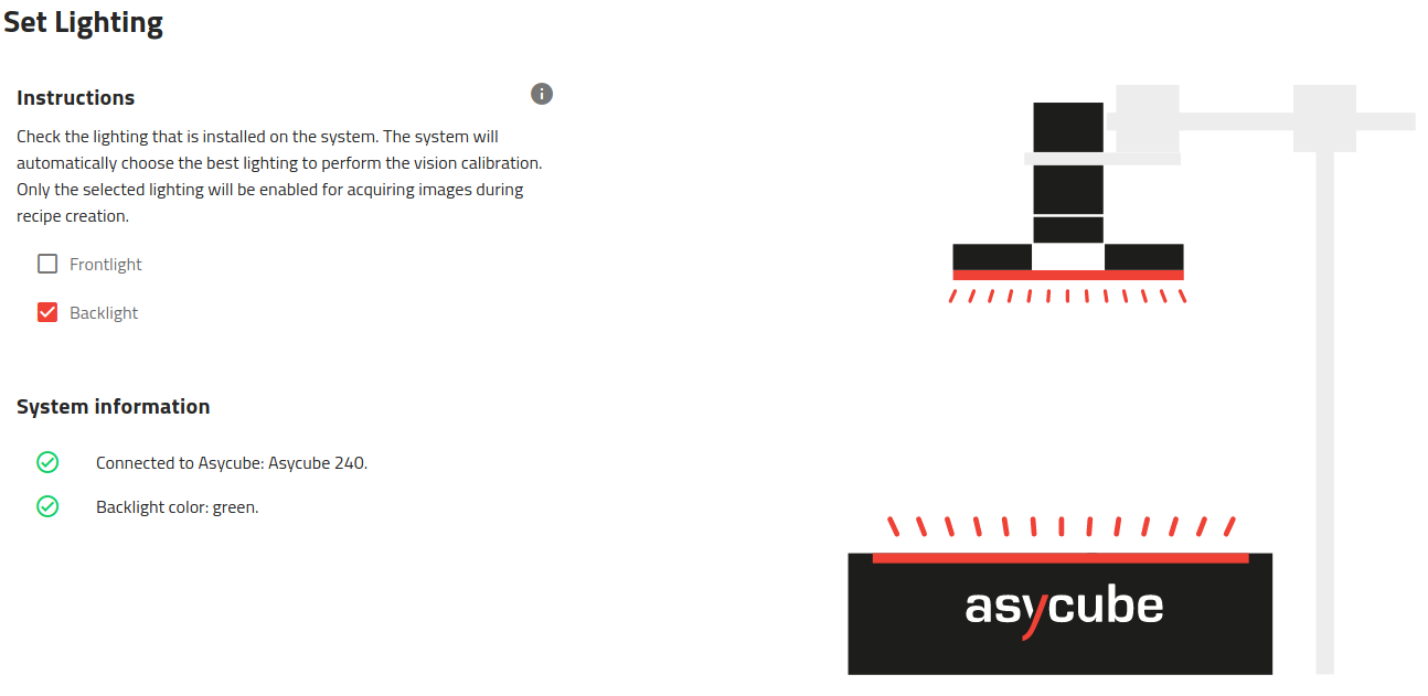
Fig. 147 Set lighting
3. Set aperture
Adjust the camera aperture to 5.6. This aperture is well adapted to the camera and lens provided in the EYE+ kit to achieve optimal contrast in the images. Then you can lock this aperture value using the top screw of the lens.
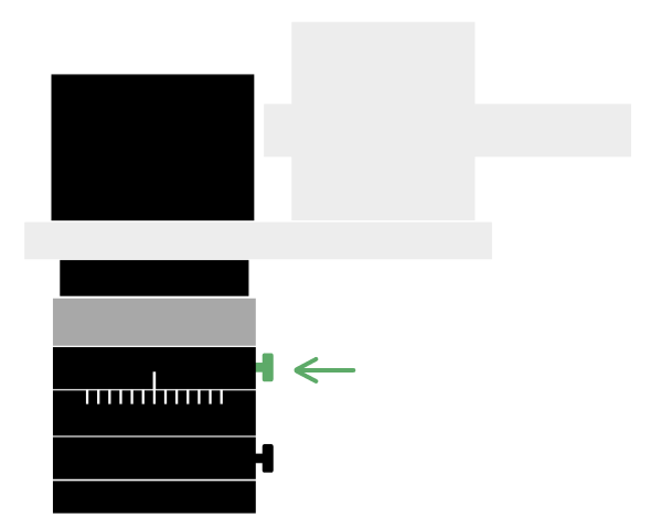
Fig. 148 Set aperture
4. Center position
Check here if your vision system is properly mounted. If it is not, you will need to adjust your installation properly.
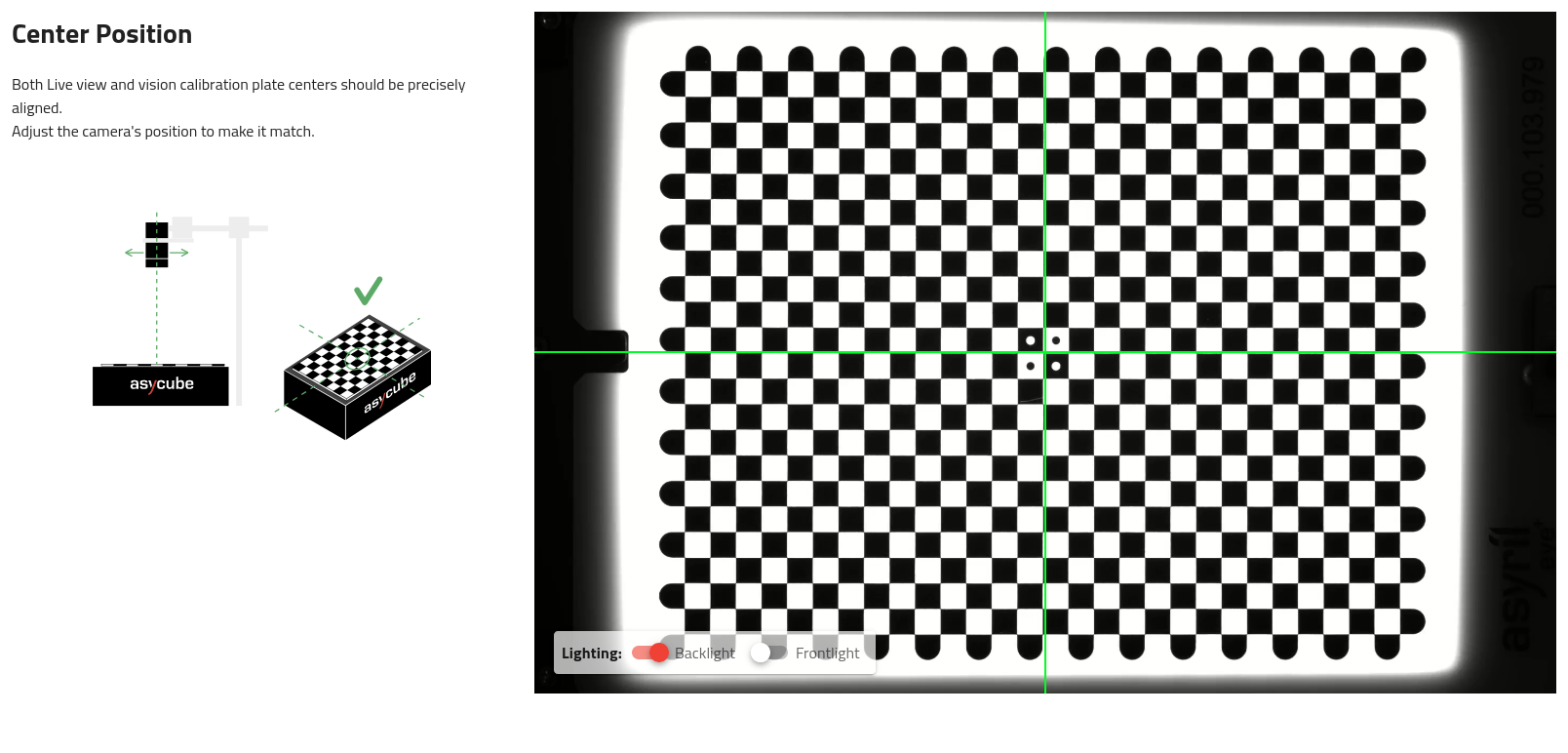
Fig. 149 Center position
Tip
If the calibration plate is not correctly visible (too dark), turn on the backlight.
You must adjust the position of the camera until the center of the green cross is roughly in the center of the vision calibration plate. Once this is done, the camera can be rigidly fixed. Never move the camera after this.
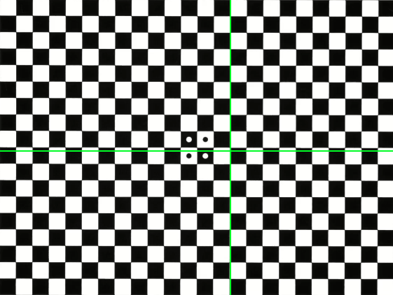
Fig. 150 Not well centered
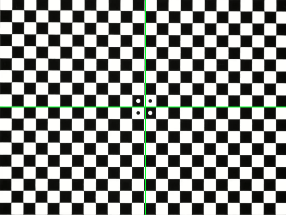
Fig. 151 Well centered
Note
The camera configuration is robust enough so that the edges of the calibration plate can be partially occluded. Up to one line can be occluded on the long axis and up to 3 lines on the short axis. This kind of situation occurs, for example, if you have a partially overlapping hopper on the plate.
However, if too many lines are occluded, the system will display a generic error message: “Unable to perform vision calibration”.
5. Set Asycube orientation
You must orient the image so that the connectors are on the left side (green rectangle in Fig. 152). Invert the camera using the switch if the connectors are on the wrong side.
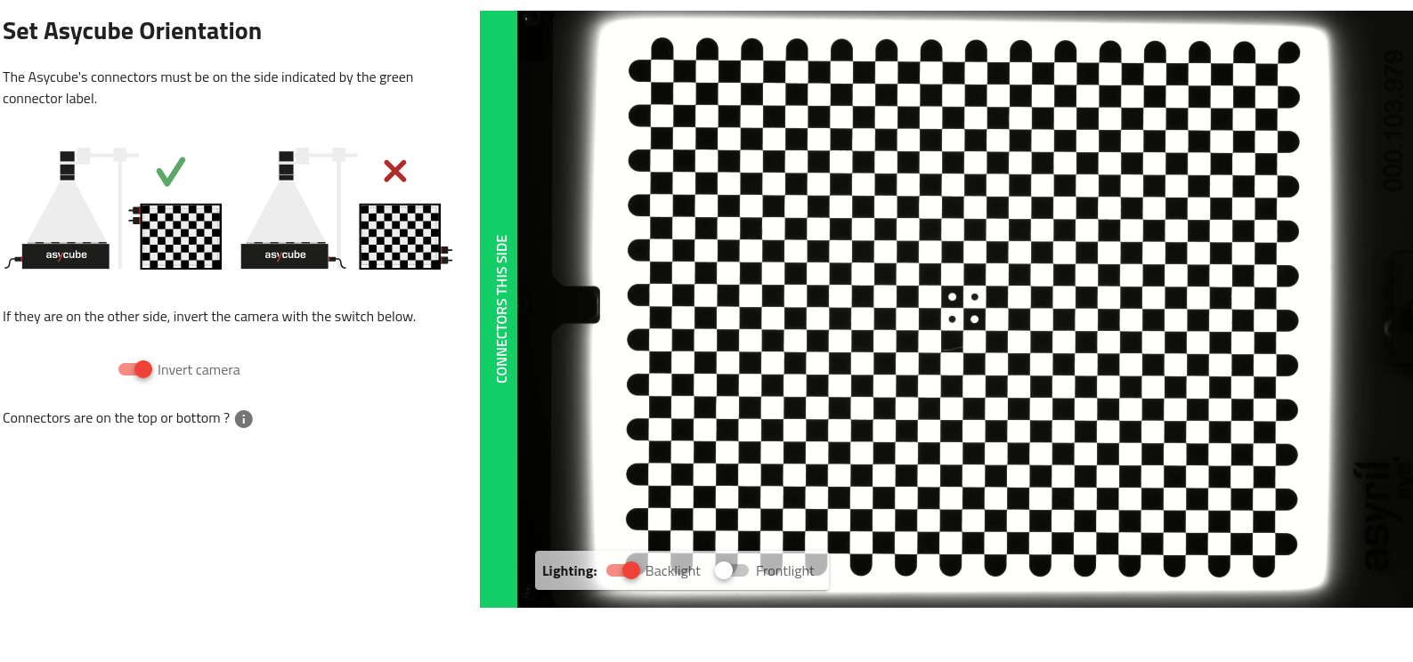
Fig. 152 Live view on the Asycube: the connectors must be placed on the same side as the green rectangle.
Warning
If the connectors are on the top or bottom, this means that the mounting of your camera is incorrectly oriented (shifted by 90°). The system will display an error during vision calibration.
The EYE+ logo of the camera must be oriented opposite the Asycube connectors (Fig. 20).
6. Adjust focus
Adjust the focus until the image is as sharp as possible. Then you can fix this focus value with the bottom screw of the lens.
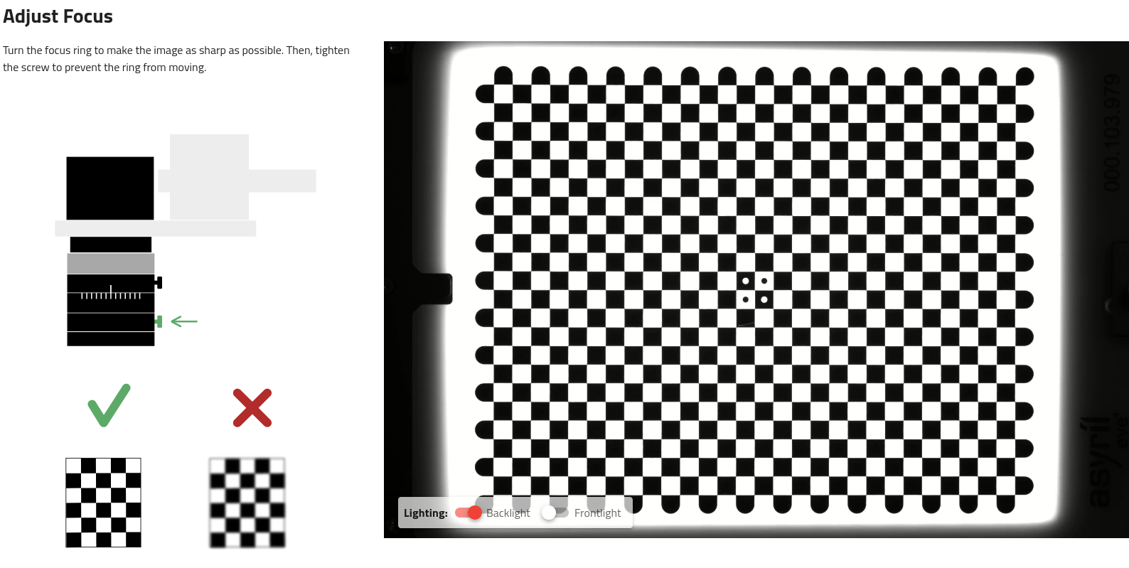
Fig. 153 Adjust focus
Warning
If you do not perform this step correctly, you may reduce the performance of image analysis.
Tip
If the calibration plate is not correctly visible (too dark), turn on the backlight.
7. Measure working distance
Measure the distance from the calibration plate to front face of the lens. This working distance is required in order to correct the parallax effect on your parts. Enter this measurement value in the interface.
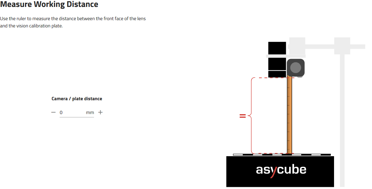
Fig. 154 Measure the working distance
Note
For more information about what parallax effect is and how it is corrected, refer to the section Parallax correction.
8. Perform vision calibration
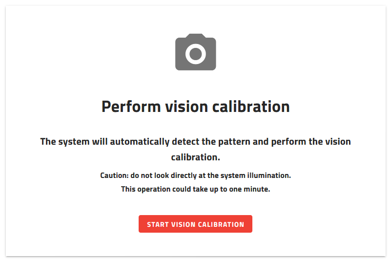
Fig. 155 Perform vision calibration
Make sure that the field of view of the plate is clear and then click .
This step starts the vision calibration. It will take into account the parameters previously input. Vision calibration applies corrections to the image using the checkerboard printed on the vision calibration plate. The vision calibration performs:
Distortion correction
RMS error of the distortion correction calculation
Region of interest (ROI) definition
Pixel-millimeter or pixel-inch scale calculation
Parallax correction
Note
Refer to section What performs vision calibration? to have more information about the vision corrections.
9. Camera configuration results
On the camera configuration results, you can see one image before and one image after vision calibration (Fig. 156).
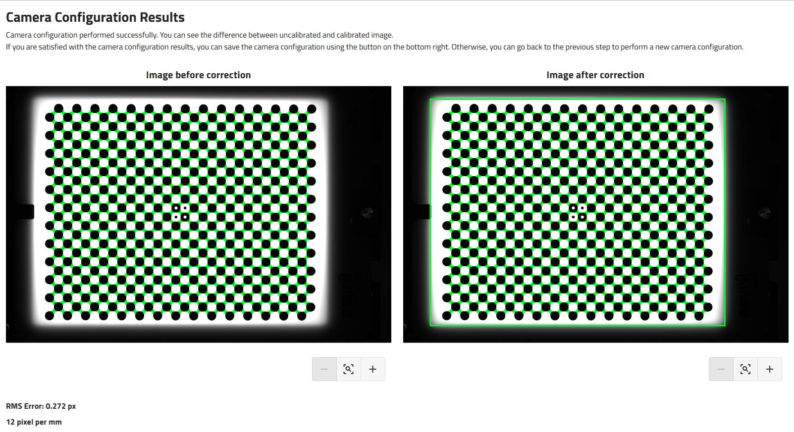
Fig. 156 Camera configuration result
Note
The before/after image presented might be very similar as the lenses we have selected for the vision kit have a very little fish-eye effect.
The green rectangle on the right image represents the region of interest.
The RMS error and the pixel-millimeter or pixel-inch scale are displayed here.
Warning
If the RMS error is greater than 1, the correction is not applicable.
If you are satisfied with the results, you can click on the to save and close the wizard.