Warning
You are reading an old version of this documentation. If you want up-to-date information, please have a look at 5.3 .Example - Beckhoff TwinCAT
This section gives an example of a simple integration of EYE+ with the EtherCAT module in Beckhoff TwinCAT version 3.1.
Prerequisites
The following example is based on the version 3.1 of Beckhoff TwinCAT, please make sure your version is up to date.
- Before you start, please make sure you have downloaded the following files:
EYE+ EtherCAT ESI file (electronic datasheet)
Optionally, EYE+ TwinCAT Project template, containing predeclared variables for easier integration
These files can be downloaded from EtherCAT Downloads.
Once you have downloaded the necessary files, please make sure to install the ESI file in the Beckhoff TwinCAT’s installation folder:
<path_to_twincat_install>\3.1\Config\Io\EtherCAT
Where <path_to_twincat_install> is usually C:\TwinCAT\ .
After installing the ESI file in the correct folder, please make sure you have restarted Beckhoff TwinCAT.
Basic integration
Once everything is in place, you can proceed with creating a new Beckhoff TwinCAT project. Then, make sure you are in Configuration Mode by pressing the following icon in the top left part:
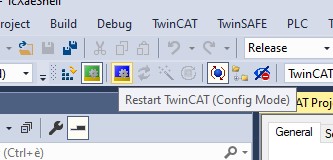
After that, you are ready to scan the EtherCAT bus to recognize and locate your EYE+ and the master device. The scan option is available by right-clicking on Devices, located in the left pane:
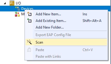
The scanning process might take a few seconds, it will find all the devices currently connected to the bus.
Note
If you do not see your EYE+ in the list after the scan has finished, please make sure it is correctly connected and powered-on. If the problem persists, please contact our support team.
After the scan is completed, you should see your EYE+ box in the list under Devices:
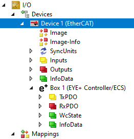
If you have downloaded the optional template, please follow the next steps. Importing the template creates all the necessary variables to fully take advantage of your EYE+. Importing the template is straightforward, right click on your PLC project an click on Import From ZIP:
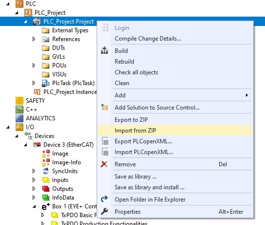
If successful, you should have entire structures of variables available:

You will need to build the project so that the variables are available from within TwinCAT. Mapping the variables to EYE+’s own variables can be achieved easily with the Multi Link functionality:
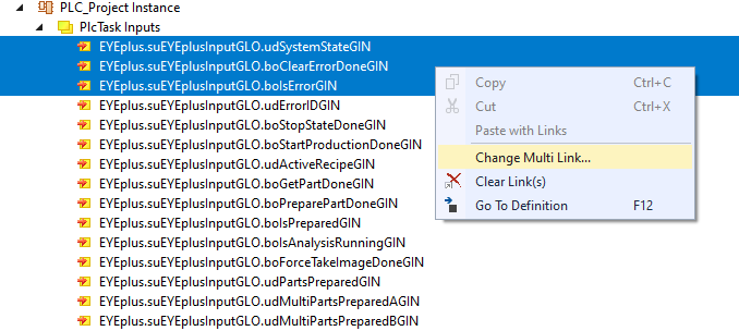
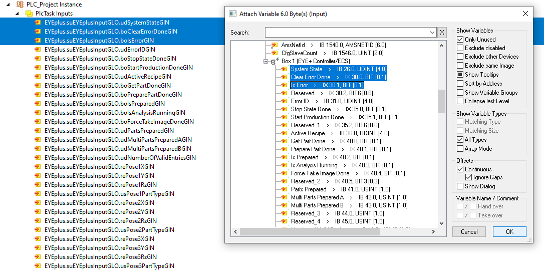
Once the variables have been mapped, and after restarting in running mode, you should be able to get live feedback of the registers:
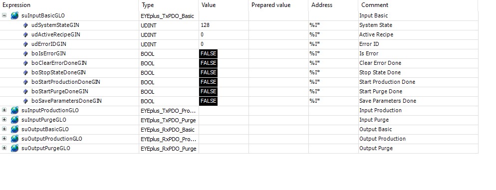
The following sample code allows you to start a production and get your first parts.
Note, the variable udRecipeID shall be set to your recipe ID.
(*
 * This sample code is distributed under the license CC0 1.0 Universal,
 * you can get a copy of the license at https://creativecommons.org/publicdomain/zero/1.0/
 *
 * THE SOFTWARE IS PROVIDED "AS IS", WITHOUT WARRANTY OF ANY KIND, EXPRESS
 * OR IMPLIED, INCLUDING BUT NOT LIMITED TO THE WARRANTIES OF
 * MERCHANTABILITY, FITNESS FOR A PARTICULAR PURPOSE AND NONINFRINGEMENT.
 * IN NO EVENT SHALL THE AUTHORS OR COPYRIGHT HOLDERS BE LIABLE FOR ANY
 * CLAIM, DAMAGES OR OTHER LIABILITY, WHETHER IN AN ACTION OF CONTRACT,
 * TORT OR OTHERWISE, ARISING FROM, OUT OF OR IN CONNECTION WITH THE
 * SOFTWARE OR THE USE OR OTHER DEALINGS IN THE SOFTWARE.
 *)

 VAR CONSTANT
         STATE_WAIT_CMD: UDINT := 0;
         STATE_START_PRODUCTION: UDINT := 10;
         STATE_GET_PART: UDINT := 20;
         STATE_READ_COORDINATES: UDINT := 30;
 END_VAR

 VAR
         //Input EYE+ controller
         suEYEplusInputGLO: EYEplus_TxPDO;
         //Output EYE+ controller
         suEYEplusOutputGLO: EYEplus_RxPDO;
         eState: UDINT := STATE_WAIT_CMD;
         udRecipeID: UDINT;
         boStartProduction: BOOL;
         boGetPart: BOOL;
         reRobotTargetX: REAL;
         reRobotTargetY: REAL;
         reRobotTargetRz: REAL;
         fbRTrig_StartProductionDone: R_TRIG;
         fbRTrig_GetPartDone: R_TRIG;
 END_VAR

 (* --------------------------------------------------------------------------------------- *)

 // Monitor rising edge of the Done flag for the "start production" command.
 fbRTrig_StartProductionDone(CLK := suEYEplusInputGLO.boStartProductionDoneGIN);

 // Monitor rising edge of the Done flag for the "get_part" command.
 fbRTrig_GetPartDone(CLK := suEYEplusInputGLO.boGetPartDoneGIN);

 CASE eState OF
         // State: waiting to receive a command from the PLC application.
         STATE_WAIT_CMD:
                 IF boStartProduction THEN // Command Start Production set.
                         boStartProduction := FALSE;
                         eState := STATE_START_PRODUCTION;
                 ELSIF boGetPart THEN // Command Get Part set.
                         boGetPart := FALSE;
                         eState := STATE_GET_PART;
                 END_IF

         // State: send a "start production" command to EYE+ and wait for completion.
         STATE_START_PRODUCTION:
                 // Set recipe ID according to EYE+ Studio.
                 suEYEplusOutputGLO.udRecipeIDGOU := udRecipeID;

                 // Send "start production" command to EYE+.
                 suEYEplusOutputGLO.boStartProductionTriggerGOU := TRUE;

                 // Wait for EYE+ response after command completion.
                 IF fbRTrig_StartProductionDone.Q THEN
                         // Reset command.
                         suEYEplusOutputGLO.boStartProductionTriggerGOU := FALSE;
                         eState := STATE_WAIT_CMD;
                 END_IF

         // State: send a "get_part" command to EYE+ and wait for completion.
         STATE_GET_PART:
                 // Send "get_part" command to EYE+.
                 // EYE+ looks for the number of parts set in "usPartQuantityGIN".
                 suEYEplusOutputGLO.boGetPartTriggerGOU := TRUE;

                 // Wait for EYE+ response after command completion.
                 IF fbRTrig_GetPartDone.Q THEN
                         // Reset command.
                         suEYEplusOutputGLO.boGetPartTriggerGOU := FALSE;
                         eState := STATE_READ_COORDINATES;
                 END_IF

         // State: read the coordinates returned by the EYE+ "get_part" command.
         STATE_READ_COORDINATES:
                 // Read coordinates returned by the "get_part" command.
                 reRobotTargetX  := suEYEplusInputGLO.rePose1XGIN;
                 reRobotTargetY  := suEYEplusInputGLO.rePose1YGIN;
                 reRobotTargetRz := suEYEplusInputGLO.rePose1RzGIN;

                 eState := STATE_WAIT_CMD;
 END_CASE