Warning
You are reading an old version of this documentation. If you want up-to-date information, please have a look at 5.4 .Hand-eye calibration - good practices
Robot coordinate frame (RCF)
The robot frame can be anywhere, it will not change the hand-eye calibration performance. However, we advise you to have:
Robot frame in the same plane as the Asycube: Place the Z=0 of the robot frame at the same level as the Asycube plate.
The positioning of the robot to pick up a part will only be the coordinates provided by EYE+ \((x,y)\) added to the picking height of the part \(z\) for your robot application.
Placing the RCF on the Asycube plate guarantees the validity of the \(z\) coordinates added manually. If the world coordinate frame is used instead, Asycube plate may not be perfectly parallel to the base of the robot. This means that the \(z\) coordinate might depend on the \((x,y)\) coordinates.
Robot frame origin in one of the four Asycube corner: Coordinates sent by EYE+ are easier to visualize when the origin is in a corner (Fig. 260).
Tool center point (TCP)
The coordinate system is used to help the robot move in space. Without tools or grippers on the robot, the end of the arm is used as the reference point for motion control (TCP on the last joint of the robot).
The controller can move each of the robot joints simultaneously to make the reference point move in space to requested positions. When you add a tool or a gripper to the robot arm, the reference point must change to reflect the offset made by the tool. A Tool Center Point or (TCP) is used to create the required offset. This allows the controller to move the coordinate system to follow the tool instead of the end of the arm.
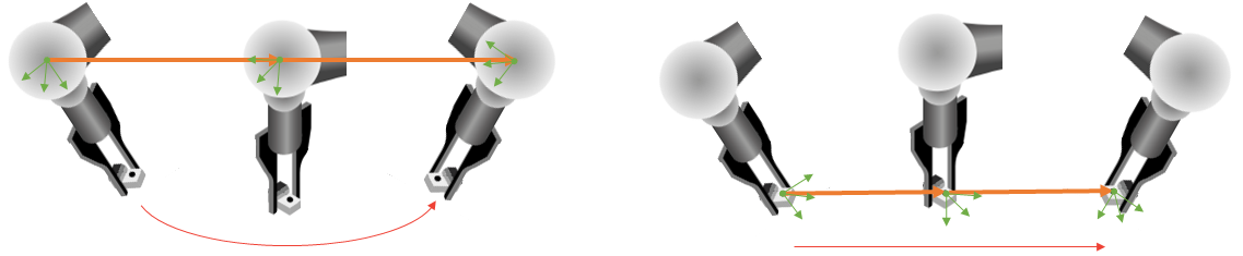
Fig. 259 left: TCP on last robot joint; right: TCP with the tool offset
Tool coordinate frame (TCF)
The tool coordinate frame is positioned on the Tool center point (TCP). Usually the Z-vector of the TCF is oriented opposite to the robot last joint or opposite to the robot tool. TCP position is the position where you want to grip the part.
Some TCP examples:
Finger gripper: Position of the TCP where the gripper will grab the part (Fig. 260).
Vacuum gripper: Position of the TCP at the end of the gripper.
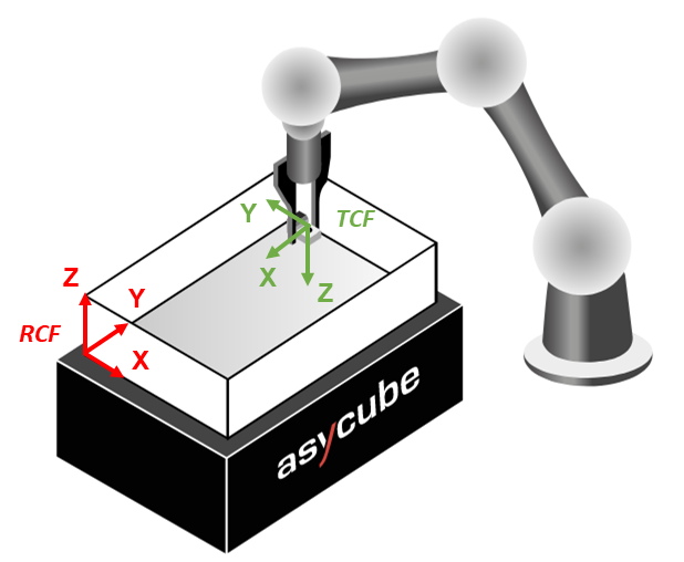
Fig. 260 RCF and TCF position. Green coordinate system: TCF; Red coordinate system: RCF
RZ angle correction
EYE+ aligns the x-axis of the TCF to the x-axis of the frame used during the hand-eye calibration (usually RCF). The RZ angle is therefore corrected to accommodate any offset between the TCF and the frame used during hand-eye calibration.
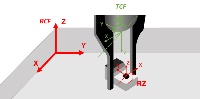
Fig. 261 rz-angle sent by EYE+
In case of static error, how to correct the RZ angle?
EYE+ cannot accommodate for offset between the frame that was used during the hand-eye calibration (usually RCF) and the TCF. Therefore a static offset might be required. The following Figure demonstrates this situation: RCF and TCF are not aligned.
You can either move your TCF in the right orientation, or correct the static error every time you get the angle by EYE+.
To find the static correction, follow the steps below :
Place a part with your gripper on the Asycube (can be anywhere with any orientation).
When the part is correctly placed, keep in mind the RZ angle given by your robot.
Move the robot out of the field of view without moving the part and check the angle sent by EYE+ by sending the command get_part from the EYE+ TCP terminal.
Note
If you do not know how to do it, please refer to section TCP programming guide.
On the robot side, apply a static correction to have the same angle on the robot and on EYE+.
Check the correction by moving the part to a different orientation. The robot and the EYE+ should show the same value.
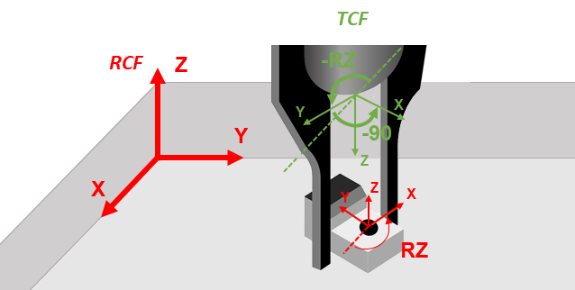
Fig. 262 rz angle sent by EYE+ with TCF having an offset of 90° with the expected one
How can I increase hand-eye calibration accuracy?
Using a part dedicate for hand-eye calibration
Part that guides the gripper: You can use a specific part to perform the hand-eye calibration. Fig. 263 is an example of a part that guides the tip of the gripper to a specific position. This way, the positioning of the gripper is more precise.
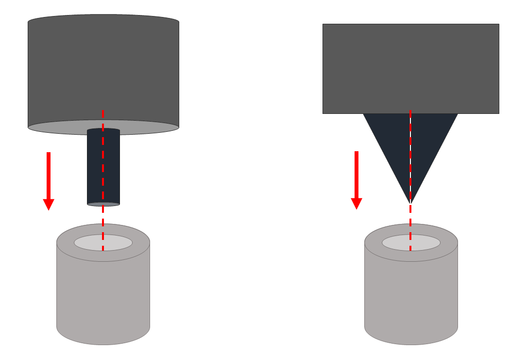
Fig. 263 Example of part that guides the gripper
Part that has a basic shape: Basic shape ensure the picking position coordinates in the recipe.
Part with small height: If the part has a small height, the parallax correction will not be taken into account for the picking position. This minimizes positioning error.
Make sure to place the tip of the gripper in the exact same position as the picking position.
Note
If your TCP is not positioned at the end of the gripper, try to orientate the gripper as vertically as possible.
Note
If you use a specific part only to perform the hand-eye calibration, there is no need to finish the recipe until the end. You can stop recipe edition after the picking position step.
Important
If you do not have the same gripper in hand-eye calibration as in production, please make sure to take into account their different TCP.
Part positioning
Position in the plate: Place the 4 parts as far away from each other as possible without touching the edge of the Asycube. The 4 best positions are in each corner of the Asycube. The more different the 4 coordinates, the better the calibration.
Relative position: The part must not move between robot coordinates acquisition and vision coordinates acquisition.