Warning
You are reading an old version of this documentation. If you want up-to-date information, please have a look at 5.4 .GPIO
The GPIO connector of the EYE+ Controller is designed to be used for Multi-feeding applications, together with the GPIO cable.
Pinout
The following illustration shows the pinout of the male GPIO connector present on the EYE+ Controller.
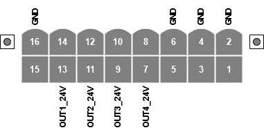
Fig. 36 GPIO pinout of the male connector, viewed from the side of the EYE+ Controller
The labeled pins have a dedicated usage attached to them which sometimes requires a specific configuration in EYE+. The usage of the currently supported pins is described in Table 21.
Pin |
Designation |
Usage |
|---|---|---|
1 |
+24VDC_GPIO |
Reserved for 24V output. Do not use! |
3 |
+12VDC_GPIO |
Reserved for 12V output. Do not use! |
5 |
+5VDC_GPIO |
Reserved for 5V output. Do not use! |
7 |
OUT4_24V |
Hopper output (e.g. multi-feeding, see 7.2 Hopper Tuning) |
9 |
OUT3_24V |
Hopper output (e.g. multi-feeding, see 7.2 Hopper Tuning) |
11 |
OUT2_24V |
Hopper output (e.g. multi-feeding, see 7.2 Hopper Tuning) |
13 |
OUT1_24V |
Hopper output (e.g. multi-feeding, see 7.2 Hopper Tuning) |
Important
The unlabeled pins (8, 10, 12, 14, 15) are reserved for future use and must be left unconnected. Failure to comply with this instruction may result in permanent damage to the EYE+ Controller or to your own device.
Power specifications
Table 22 summarizes the EYE+ Controller power specifications for the GPIO connector.
Pin |
Designation |
Max current |
|---|---|---|
7 |
OUT4_24V |
500mA |
9 |
OUT3_24V |
500mA |
11 |
OUT2_24V |
500mA |
13 |
OUT1_24V |
500mA |
Important
The maximum current that can be delivered by the entire connector at once is 1.25A. That means the values for max current are reduced when all outputs are used at once.
Important
Never attempt to draw more power from the outputs than specified in Table 22. This might result in permanent damage to the EYE+ Controller.