Warning
You are reading an old version of this documentation. If you want up-to-date information, please have a look at 5.4 .GPIO
GPIO cable
In the context of Dualfeeding, two hoppers are required. The easiest solution is to connect both hoppers to the Asycube. However, in some cases, e.g. when using the purge on an Asycube 240, it is not possible to connect two hoppers to the Asycube. For such cases, Asyril SA proposes an optional cable to connect the hoppers to the EYE+ Controller. The cable connects the GPIO connector of the EYE+ Controller on one side and the M8 cables from the hoppers on the other side.
The M8 cables from the hoppers are connected to a distribution box. This box has a 3 meters long cable ending with an 8-position female GPIO connector with 16 contacts (2 rows), 3.5 mm pitch, that is plugged to the GPIO connector on the EYE+ Controller.
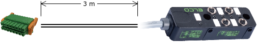
Fig. 36 Dualfeeding cable
The distribution box has mounting holes that can be used to fasten the box:
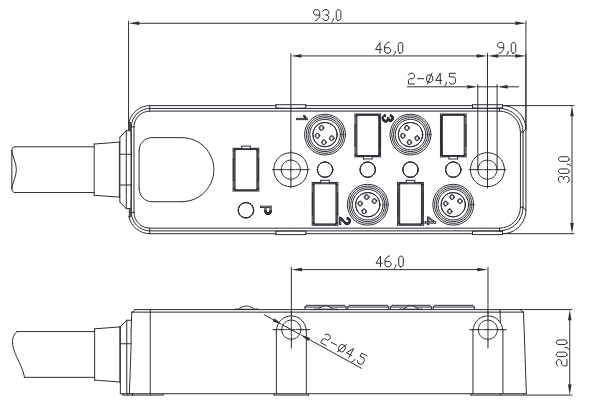
Fig. 37 Distribution box schematic
Important
Only connect an Asyril hopper using the supplied M8 cable to the distribution box. Do not connect any other hopper or use any other cable. Failure to comply with this instruction may result in permanent damage to the EYE+ Controller or to your own device.
Pinout
The following illustration shows the pinout of the male GPIO connector present on the EYE+ Controller.
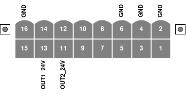
Fig. 38 GPIO pinout of the male connector, viewed from the side of the EYE+ Controller
The labeled pins have a dedicated usage attached to them which sometimes requires a specific configuration in EYE+. The usage of the currently supported pins is described in Table 21.
Pin |
Designation |
Usage |
|---|---|---|
11 |
OUT2_24V |
Hopper output (e.g. dualfeeding, see 7.2 Hopper Tuning) |
13 |
OUT1_24V |
Hopper output (e.g. dualfeeding, see 7.2 Hopper Tuning) |
Important
The unlabeled pins (1, 3, 5, 7, 8, 9, 10, 12, 14, 15) are reserved for future use and must be left unconnected. Failure to comply with this instruction may result in permanent damage to the EYE+ Controller or to your own device.
Power specifications
Table 22 summarizes the EYE+ Controller power specifications for the GPIO connector.
Pin |
Designation |
Max current |
|---|---|---|
11 |
OUT2_24V |
500mA |
13 |
OUT1_24V |
500mA |
Important
Never attempt to draw more power from the outputs than specified in Table 22. This might result in permanent damage to the EYE+ Controller.