Warning
You are reading an old version of this documentation. If you want up-to-date information, please have a look at 5.4 .2.1 Acquisition settings
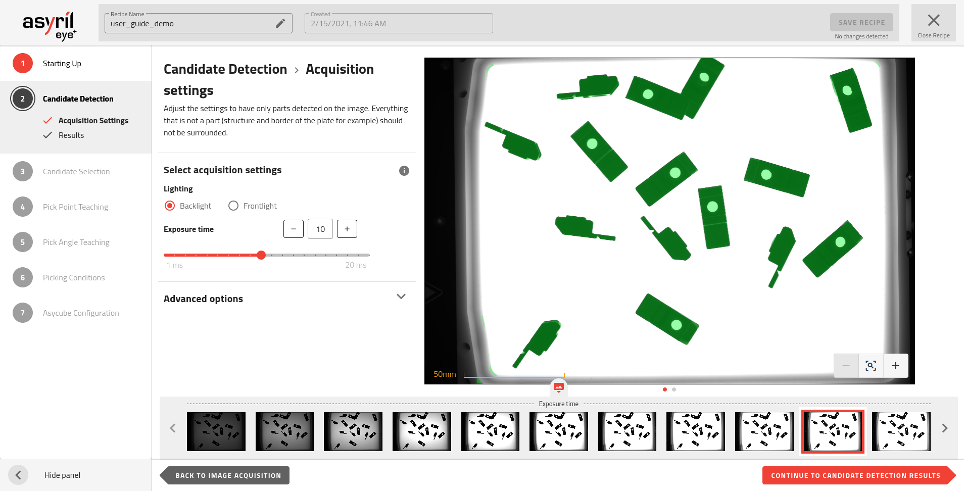
Fig. 57 Candidate Detection - Acquisition settings
Select acquisition settings
Lighting
The type of lighting must be adapted to your parts and the type of production plate you use. The choice of lighting must allow good detection of the parts and good rejection of undesired elements.
For good part detection, the lighting must highlight the edges of the parts. EYE+ detects the edges of the parts when the contrast between the part and the production plate is high.
In the Fig. 58, we see that the contrast is the best on the backlight image. This image should thus be used for the candidate detection step. Note that it is not possible to differentiate the orientation of the part on this backlight image, thus the frontlight will be used in the Candidate Selection step.
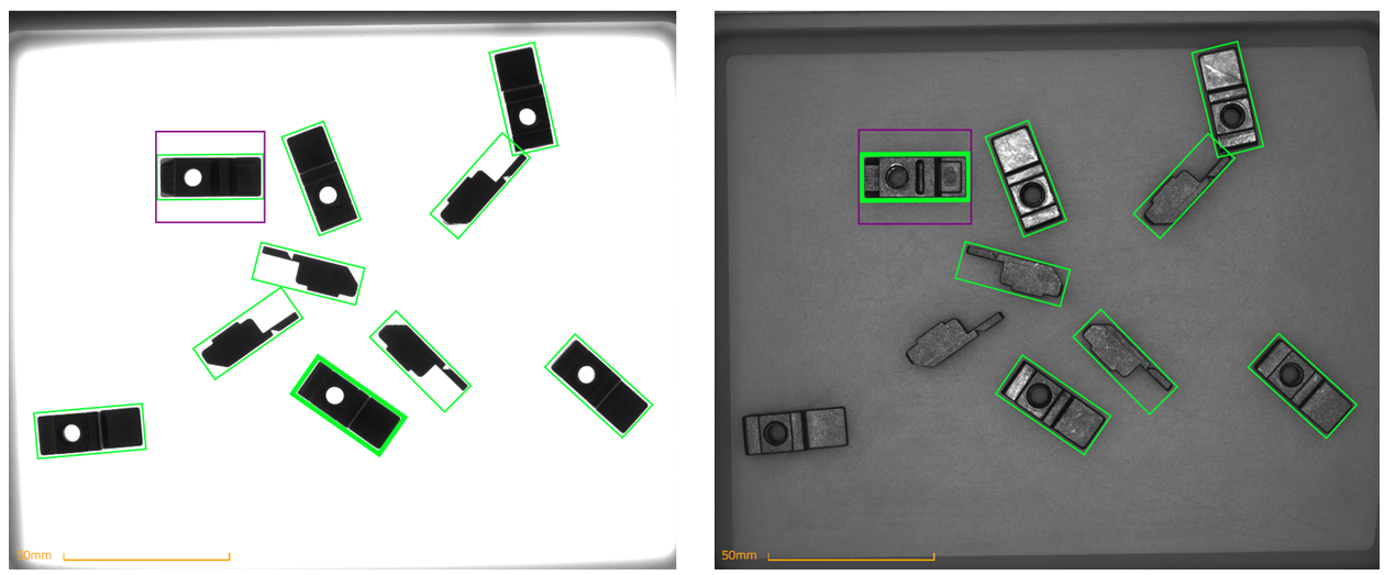
Fig. 58 Best Candidate Detection with Backlight 13ms (left) and best Candidate Selection with Frontlight 14ms (right)
Backlight
In most cases, using the backlight is adequate for part detection. This type of lighting highlights the outline of the parts, making them look like a silhouette, hence showing greater contrast between an opaque part and the translucent background of the Asycube plate.
Frontlight
In some cases, using the frontlight in this candidate detection step can be useful:
Transparent parts: If your parts are transparent, using the frontlight lets the parts reflect the incoming light, increasing contrast. The EYE+ detection algorithm will be able to detect the part if the contrast between the reflection of the part and the background is high enough.
Black production plate: In order to increase the contrast between a part and the Asycube plate it can sometimes be useful to use a black plate combined with a frontlight.
Note
Using the frontlight in a standard situation may highlight many undesirable elements that would not appear with a backlight. It is more difficult to choose the size of the parts in order to filter only the desired candidates.
Note
If the lighting settings you want to use are not available on this page, you can easily change the acquisition lighting settings in the configuration window. Once you have changed these settings, you must go back to the 1.2 Image Acquisition page and click on the to take new images with the newly defined settings.
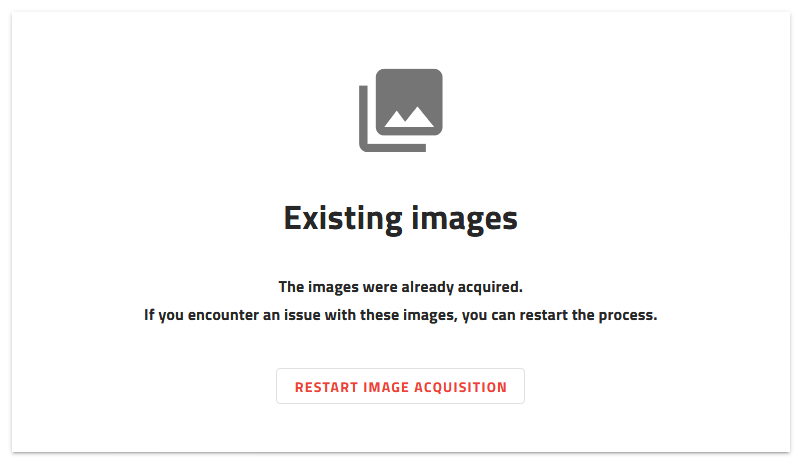
Fig. 59 Starting up - restart image acquisition
Exposure time
Exposure time is the time during which the camera is exposed to light when acquiring images. The longer the exposure time, the brighter the image.
Increasing or decreasing the exposure time affects the contrast between the parts and the production plate. You have to find the optimal exposure time for part detection.
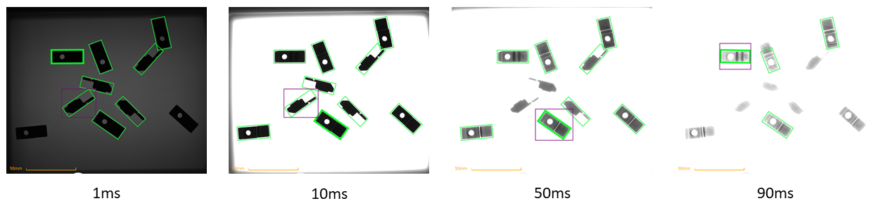
Fig. 60 Images with different exposure times using backlight
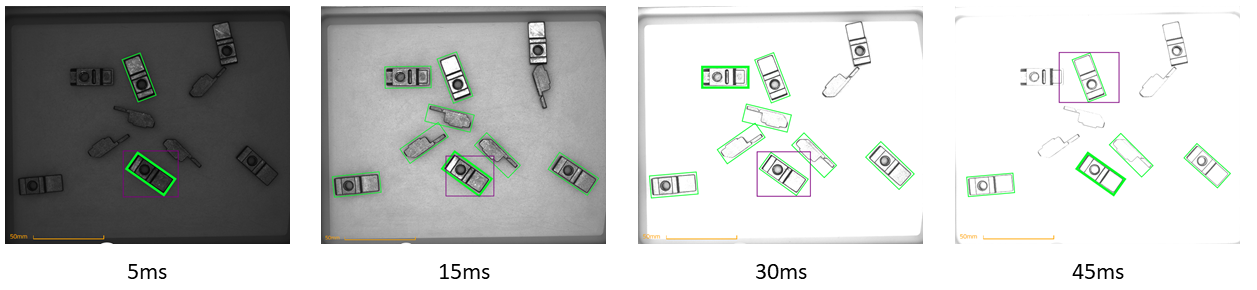
Fig. 61 Images with different exposure times using frontlight
Too short of an exposure time
The EYE+ detection algorithm may not detect parts if it cannot determine the difference between the part and the background. This occurs especially when parts are close to the borders of the plate.
The EYE+ detection algorithm could detect undesirable elements such as the shape or shadow of the production plate.
Too long of an exposure time
An over-saturated image might erode the edges of the parts. The size of the parts could then be different from one position in the image to another. Detection will not be robust enough for small part sizes.
Advanced options
The advanced options provide additional settings that can be adjusted in case the default detection settings can’t give good enough results, for example when using a structured plate and the texture of the plate is detected as parts.
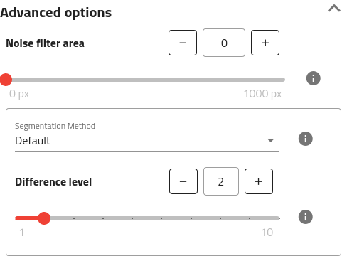
Fig. 62 Advanced options can be displayed by clicking on the top right of the title.
Important
When looking at the segmentation image, you should ideally see all parts in white and all the rest in black. This segmentation image will be later used to check for collision with other parts so it is important that as little noise as possible shows up on the image and that real parts are successfully detected.
Noise filter area
This parameter allows for filtering noise by removing everything that is smaller than the defined area. This area is expressed in calibrated unit or in pixels depending on the camera configuration.
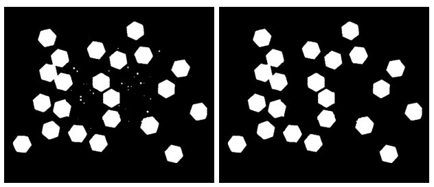
Fig. 63 Segmentation image with different noise filter area values. Left: 0px, Right: 450px.
Tip
It is easier to see if there is some noise on the image on the segmentation image. The image can be changed by clicking on the navigation buttons below the image.
Segmentation Method
The segmentation can be done using multiple methods. EYE+ currently supports 2 methods:
Default
Hard threshold
Default
Optimized segmentation method that will work for most of the parts, without the need for adjusting any parameters.
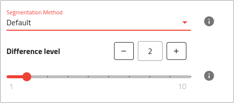
Fig. 64 Default segmentation method with available settings.
Difference level
The difference level is the maximal intensity difference between a pixel and its neighbors to consider this new pixel as belonging to the same part. The default difference level is 2. Increasing this value will sharpen the edges of the parts but can also erode the contour.
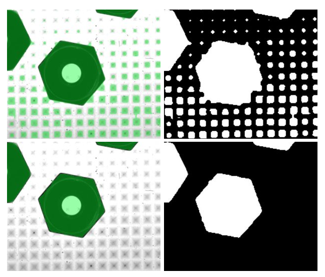
Fig. 65 Close-up of a part on a pyramidal plate (Left: Result with overlay, Right: Segmentation image) using different difference level (Top: Difference level of 2, Bottom: Difference level of 10).
Tip
Be especially careful when changing this value that parts close to the borders are not disappearing. If this happens, try to increase the exposure time or lower the difference level.
Hard threshold
This method will apply the defined threshold to differentiate the plate from the background. This works well on pictures where the intensity level of the parts differs a lot from the intensity level of the background.
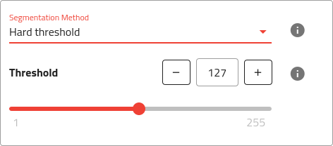
Fig. 66 Hard threshold segmentation method with available settings.
Tip
The hard threshold can be best suited for parts needing a plate with grooves or holes.
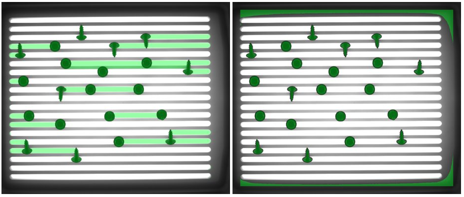
Fig. 67 Part on a plate with grooves that works better with hard thresholding method. Left: Default method, Right: Hard threshold method.
Important
This method uses a fixed threshold and is therefore sensitive to brightness changes on the image. Make sure that ambient light will not affect the image too heavily when using this method.
Note
Using this method, it is hard to avoid some area in the background being detected as potential candidates (white in the segmentation image), especially close to the borders of the plate. This is a limitation of this method.
Threshold
Intensity threshold (between 1 and 255). Adjust the threshold so that only parts are detected.
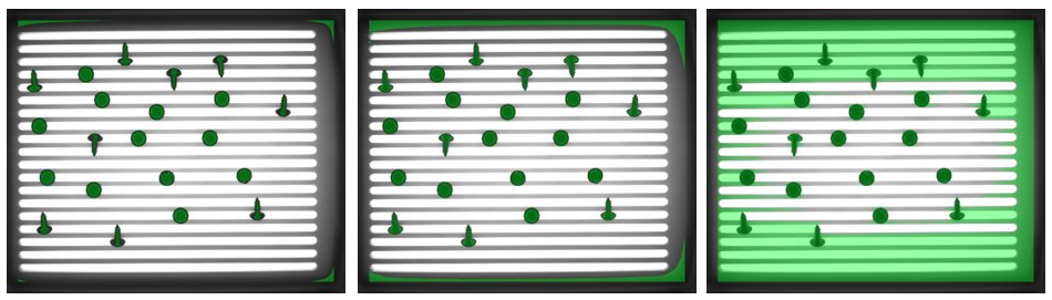
Fig. 68 Result with different threshold. Left: Threshold too low (parts are eroded), Middle: Good threshold, Right: Threshold too high (parts not separated from background).