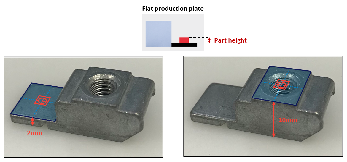
The part height you must enter in this step is the height where the pick point is placed.
EYE+ corrects the parallax effect induced by the variation of the
position of the parts on the Asycube surface by adding an offset to the X and Y coordinates according
to its position on the platform. A part located on the edge of the platform will have a greater offset than a part
located in the middle. To calculate these offsets, the system must identify the height of the part where you specified
the pick point.
Fig. 90 Part height depending on the pick point position
Note
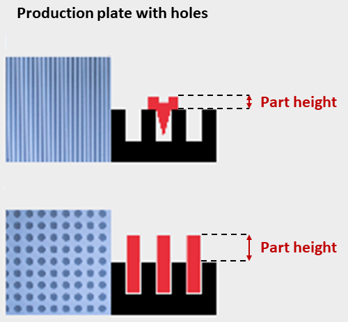
In the case of custom or structured production plates (with holes, grooves…), the part height entered
must be adapted to not take into account the height of the part located inside the plate.
Fig. 91 Part height depending on the production plate used
Similar to the part height, EYE+ also needs to account for the thickness of the
production plate used with the current part in order to correct the parallax effect. For a standard Asyril plate, this
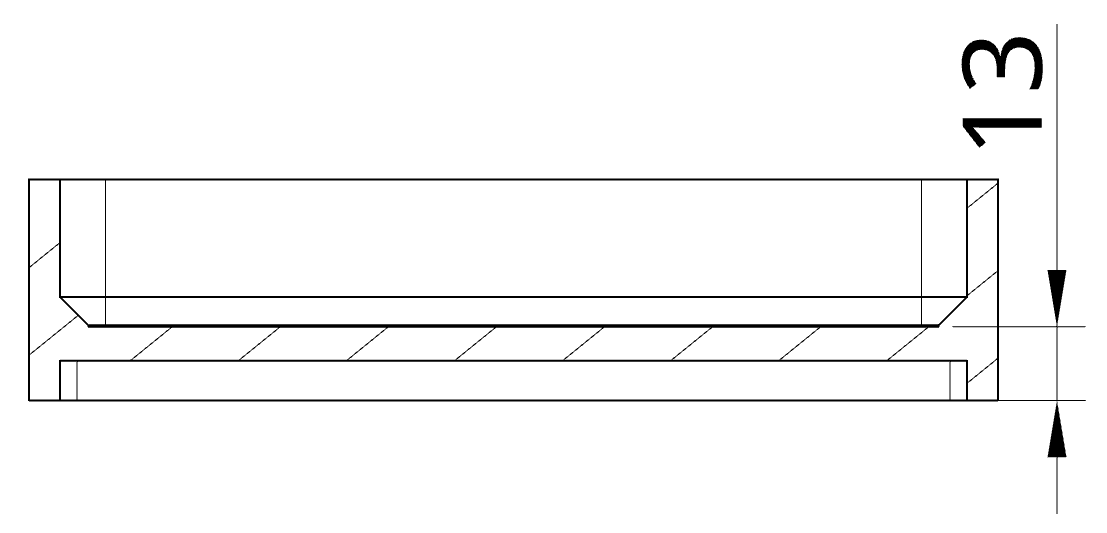
is the distance between the bottom of the plate and its surface as described on
Fig. 92 for a standard Asycube 240 plate.
Fig. 92 Height measurement for a standard Asycube 240 production plate
Per default, EYE+ will set this value to the height of the standard Asyril production plate for your Asycube type as
defined in Table 24.
If the current part requires a special plate, you will need to measure the height of this plate as described in
Fig. 92 and enter the value in the production plate height field in
EYE+.
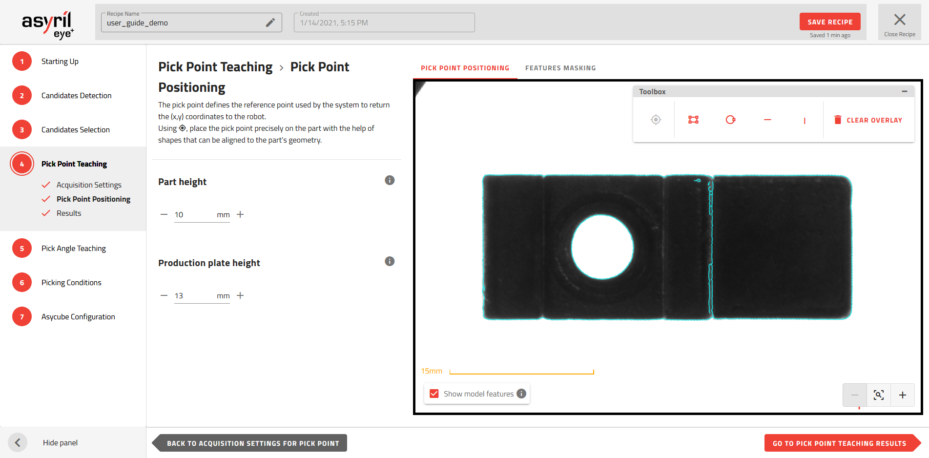
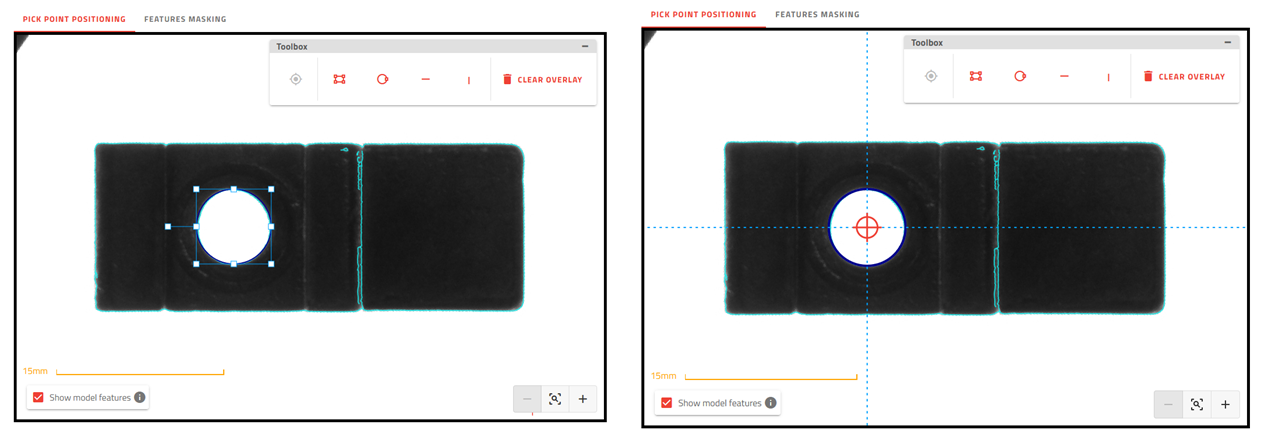
Carefully place the target on the desired pick point position. This operation must be performed carefully
because it determines the accuracy of the coordinates (X, Y) that will be sent to the robot.
Tip
Use the drawing tools to set the pick point precisely.
The coordinates returned by the get_part command will be directly corrected with the offset of
parallax if the camera configuration has been done properly.
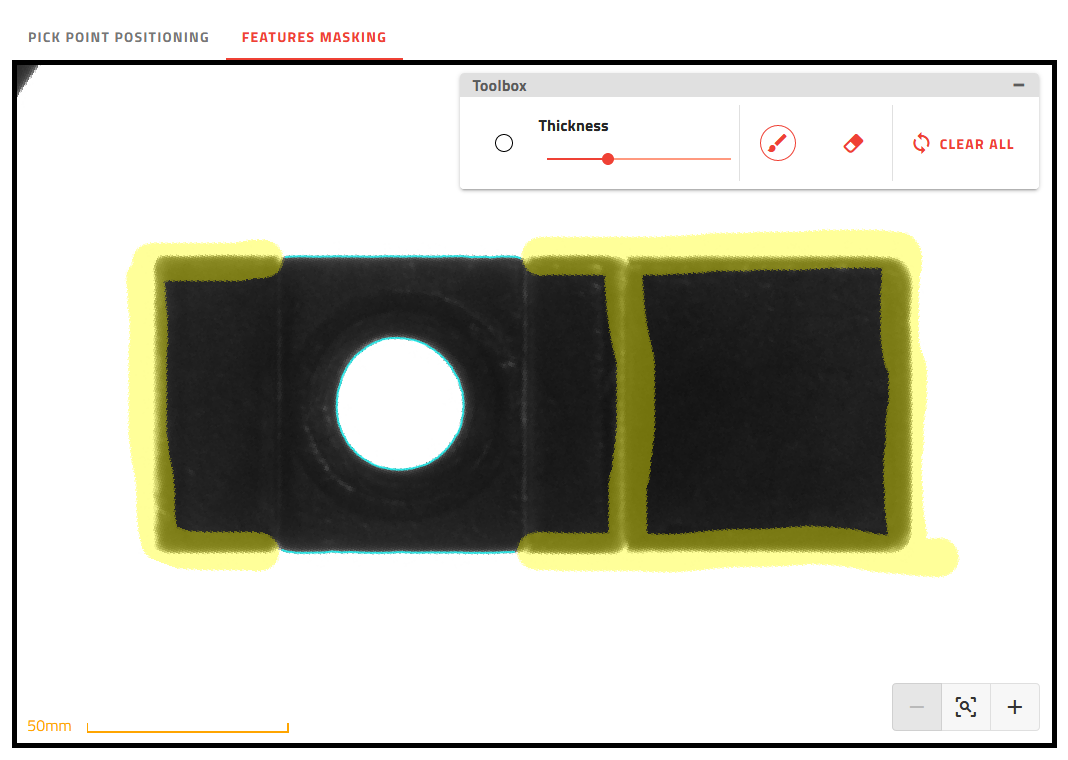
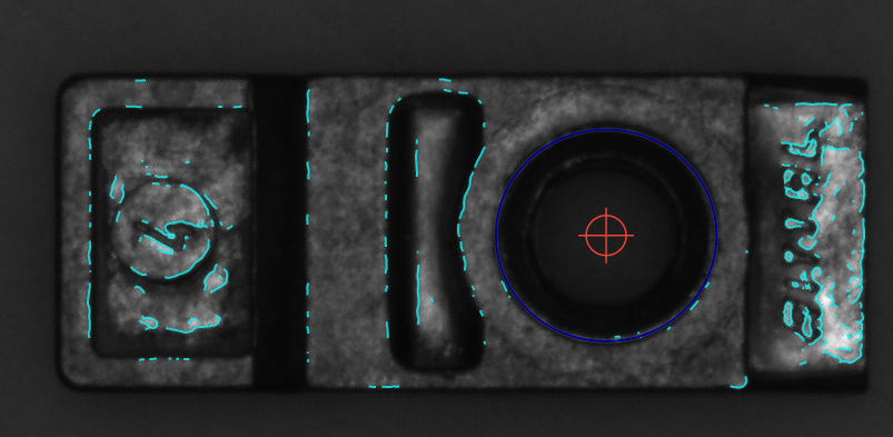
Fig. 94 Feature masking for the positioning of the pick point in the middle of the circle at the maximum height of the part
The objective of the feature masking step is to define the reference features (residual features after masking)
that will be used as a model to place the pick point.
Not all features are relevant to define the reference model.
Features at the same height: Features that are not placed at the same level as the pick point must be masked
out. We only want to detect as accurately as possible those features that are at the same height as the pick point.
Adding features that are not at the same level may alter the accuracy of the positioning of the pick point due to
parallax (these features on a different level will not always have the same relative position depending on the
position of the part in the Asycube).
Reproducible features: It is essential that the reference model reflects a general description of the
candidates. Any features that are not reproducible from one candidate to another must be masked.
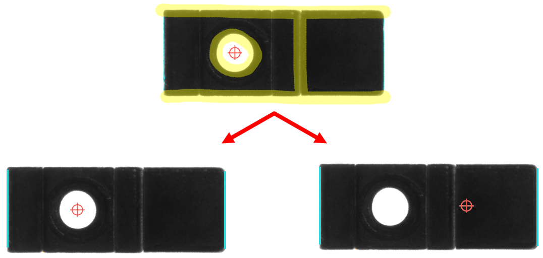
Enough features: There must be enough features to ensure that there is only one possible pick point
identified by the algorithm. For example, if you want to pick the part in the middle of the circle but you do not
inform the system about the circle features, there will be two possible pick point positions.
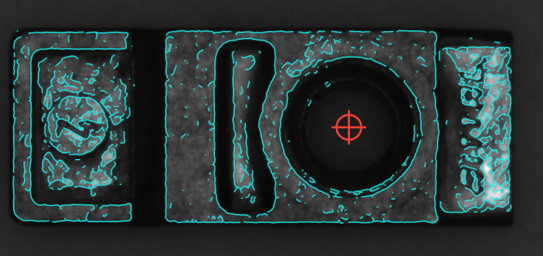
Fig. 95 Not enough features to position the pick points: 2 possibilities
The advanced options provide additional settings that can be adjusted in case the default settings do not give
good enough results, for example when some important features are not detected.
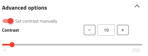
By default, EYE+ automatically determines a contrast value that is used to extract features. The contrast value of
a pixel is the gray value difference from its neighbors. If the pixel contrast exceeds the value specified, the pixel is
selected to determine the model features.
Tweaking the contrast parameter allows creating a model that has more features than the automatically-computed one. For
certain applications, it can help to precisely set the pick point.
The contrast setting can be manually set by toggling “Set contrast manually” on, as shown below:
The effect of the contrast setting is shown below:
Fig. 96 Pick point model where contrast is automatically computed by EYE+
Fig. 97 Pick point model where contrast is manually set to a lower value (e.g. 19)
Tip
The more features detected the more time it takes to run the pick angle step, remove as many features as
possible using the mask functionality.