Warning
You are reading an old version of this documentation. If you want up-to-date information, please have a look at 5.4 .Module overview
The EtherNET/IP Module is schematically equivalent to:
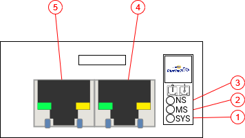
Fig. 218 EtherNet/IP Module
System LED (SYS)
Module Status LED (MS)
Network Status LED (NS)
Interface X1, standard RJ45
Interface X2, standard RJ45
LEDs Behavior
The subsequent table describes the meaning of the various LEDs found on the device.
LED |
Color |
State |
Description |
|---|---|---|---|
MS |
Off |
Off |
No power |
Green |
On |
Device operational |
|
Green |
Flashing |
Standby |
|
Red |
On |
Major fault |
|
Red |
Flashing |
Minor fault |
|
Red/Green |
Flashing |
Self-test |
|
NS |
Off |
Off |
Not powered, no IP address |
Green |
On |
Connected |
|
Green |
Flashing |
No connections |
|
Red |
On |
Duplicate IP |
|
Red |
Flashing |
Connection timeout |
|
Red/Green |
Flashing |
Self-test |
|
Ethernet LED |
Off |
Off |
No link established |
Green |
Blinking |
Module is transmitting |
|
Green |
Solid |
A link is established |
Module configuration
The module configuration can be seen under in Communication.
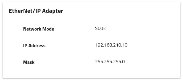
Fig. 219 EtherNet/IP Adapter configuration
Note
The IP settings are only displayed when at least one port of the module is connected otherwise N/A is displayed.
Tip
To change the IP address, use an external tool such as the Molex Industrial Communication Competence Center (ICCC) EtherNetIP Tool.
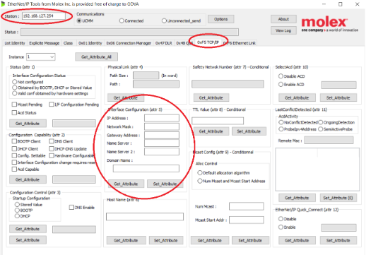
Fig. 220 Molex Industrial Communication Competence Center (ICCC) EtherNetIP Tool
Network topology
When multiple EtherNet/IP devices are to be connected, three topologies can be implemented:
- Daisy chain and/or star topology:
Modules are connected like a daisy chain where Module 1 is connected to Module 2, and so on. The last module does not require to be connected back to the master.
- Ring topology:
Modules are connected such that they form a ring, Module 1 is connected to Module 2, and so on. The last module is connected back to the EtherNet/IP Scanner, thus forming a ring.
- Tree topology:
Modules are connected such that they form a tree. A Module is the root node to which multiple Modules (branches) can be connected. The last modules (at the end of the branches) do not require to be connected back to the master.
Please, review your requirements to choose which topology best fits your needs.
Assemblies
EtherNet/IP allows exchanging cyclic real-time data using assemblies. There are two types of assemblies corresponding to the two directions: consuming and producing assemblies.
All the necessary commands, parameters and output data are implemented in assemblies so that you can easily and fully integrate your EYE+ into your application. Assemblies are mostly mirroring the TCP Protocol interface while providing a specific and convenient interface to use. We highly recommend you read the TCP programming guide before integrating EYE+ using the EtherNet/IP Module.
The EDS file can be directly downloaded from EtherNet/IP Downloads.