Warning
You are reading an old version of this documentation. If you want up-to-date information, please have a look at 5.4 .Camera and lens
Dimensions
The camera can be fixed using the four M3 mounting holes (labeled M on Fig. 17).
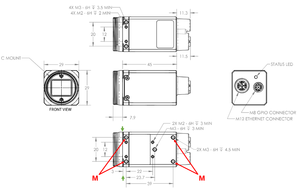
Fig. 17 Camera dimensions; M= Mounting holes
Depending on your Asycube size and your working distance, different lenses may be used. The main dimensions of the different vision kits (See Fig. 18) are summarized in Table 6 and in Table 7
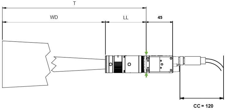
Fig. 18 Camera with cable connected dimensions [mm]; T= Total length; WD = Working distance; LL = Lens length; CC = Cable connector + cable folding length
Characteristic |
Value |
|---|---|
Weight |
67g |
Dimensions |
29 x 29 x 64.4 mm |
Storage Temperature |
-30 to 60°C |
Operating Temperature |
-20 to 55°C ambient |
Humidity |
Operating: 20% ~ 80%, relative, non-condensing |
Shock and Vibration |
DIN EN 60068-2-27, DIN EN 60068-2-64, DIN EN 60068-2-6 |
Ingress Protection |
IP67 |
Asycube |
WD: Working distance [1] |
LL: Max lens length [2] |
T: Total length |
Lens weight |
|---|---|---|---|---|
Asycube 50 |
Short: 390mm |
50 mm |
440 mm |
0.08 kg |
Long: 560mm |
95 mm |
655 mm |
0.22 kg |
|
Asycube 80 |
Short: 580mm |
50 mm |
630 mm |
0.08 kg |
Long: 850mm |
95 mm |
945 mm |
0.22 kg |
|
Asycube 240 |
Short: 790mm |
45 mm |
835 mm |
0.06 kg |
Long: 1070mm |
50 mm |
1120 mm |
0.07 kg |
|
Asycube 380 |
Short: 810mm |
45 mm |
855 mm |
0.08 kg |
Long: 1260mm |
45 mm |
1305 mm |
0.06 kg |
|
Asycube 530 |
Short: 900mm |
45 mm |
945 mm |
0.09 kg |
Long: 1260mm |
45 mm |
1305 mm |
0.08 kg |
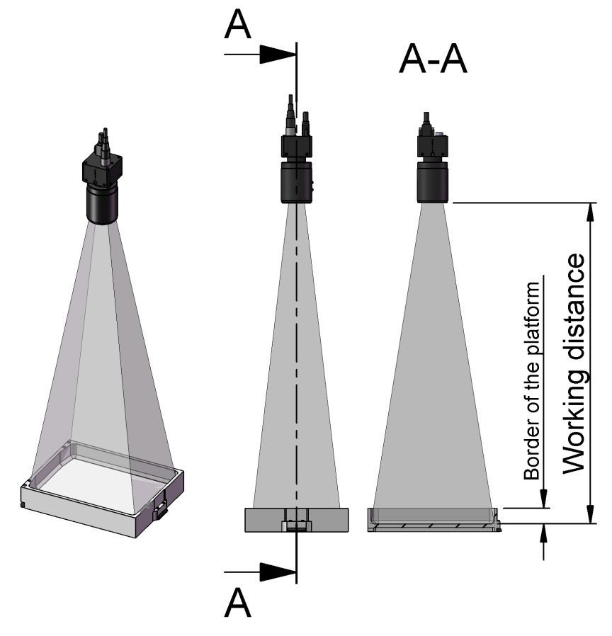
Fig. 19 Working distance
Mounting the camera and the lens
Unpack the camera and the lens. The lens is already mounted on the camera.
Fix the camera using the four M3 mounting holes (labeled M on Fig. 17).
Camera positioning
Camera must be placed orthogonal to the Asycube and above its center.
Important
The orthogonality between the camera and the Asycube is critical for accurate part detection. Particular care must be taken at this stage of installation.
Distance between the front of the lens and the Asycube plate has to correspond to the working distance (see Table 7).
Make sure that the field of view encompasses the inner edge of the plate frame. The EYE+ logo must be oriented opposite to the Asycube connectors (Fig. 20).
Important
We recommend you design the camera mounting so that it can be adjusted in x, y and z. Make sure that the camera position can be adjusted mechanically with a tolerance of -10mm/+30mm in z and -10mm/10mm in x and y.
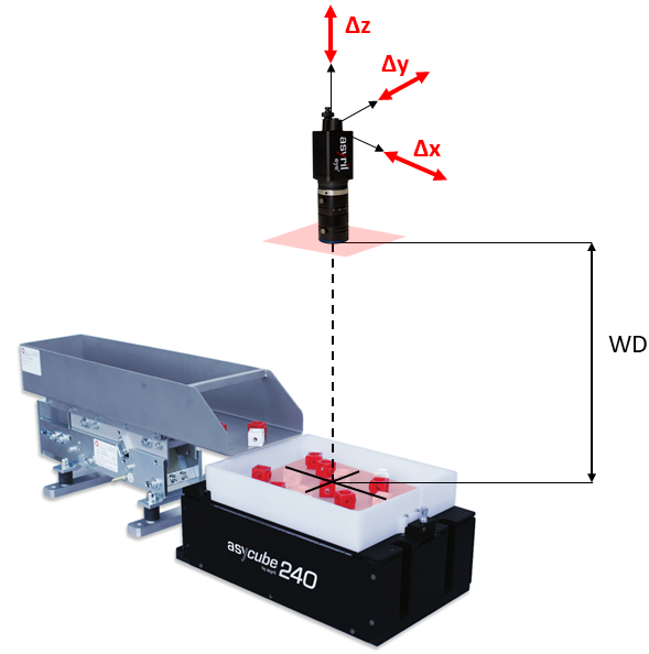
Fig. 20 Camera positioning; WD = Working Distance