Avertissement
You are reading an old version of this documentation. If you want up-to-date information, please have a look at 5.4 .Electrical interfaces
EYE+ Controller can be connected to:
Power supply
Asycube
Camera
Robot or PLC to work in production
Computer or company network for configuration
Frontlight
The overall connections are presented in Fig. 36.
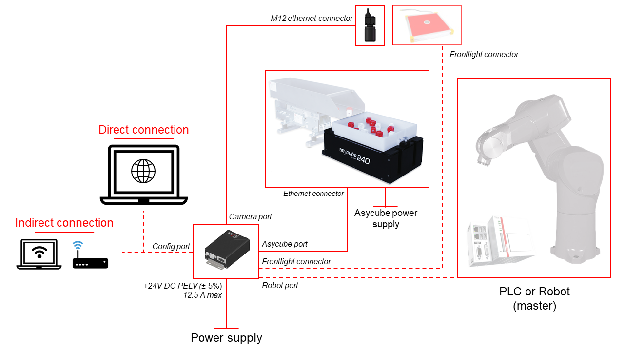
Fig. 36 EYE+ wiring diagram
Note
Communication cables can be ordered in different lengths depending on your needs.
EYE+ inputs/outputs
Four Ethernet connectors are available on EYE+ Controller :
3 for device connections: Robot, Asycube, Camera
1 for direct/indirect communication with your EYE+ Controller: Configuration
Tableau 21 shows the default Ethernet configuration.
Ethernet port |
Device connected |
IP address |
Subnet mask |
|---|---|---|---|
Robot |
Robot or PLC |
192.168.0.50 |
255.255.255.0 |
Asycube |
Asycube |
192.168.127.1 |
255.255.255.0 |
Camera |
Camera |
192.168.21.1 |
255.255.255.0 |
Config [1] |
Computer or company network |
192.168.1.50 |
255.255.255.0 |
Fig. 37 shows the different connectors on both sides of the EYE+ Controller.
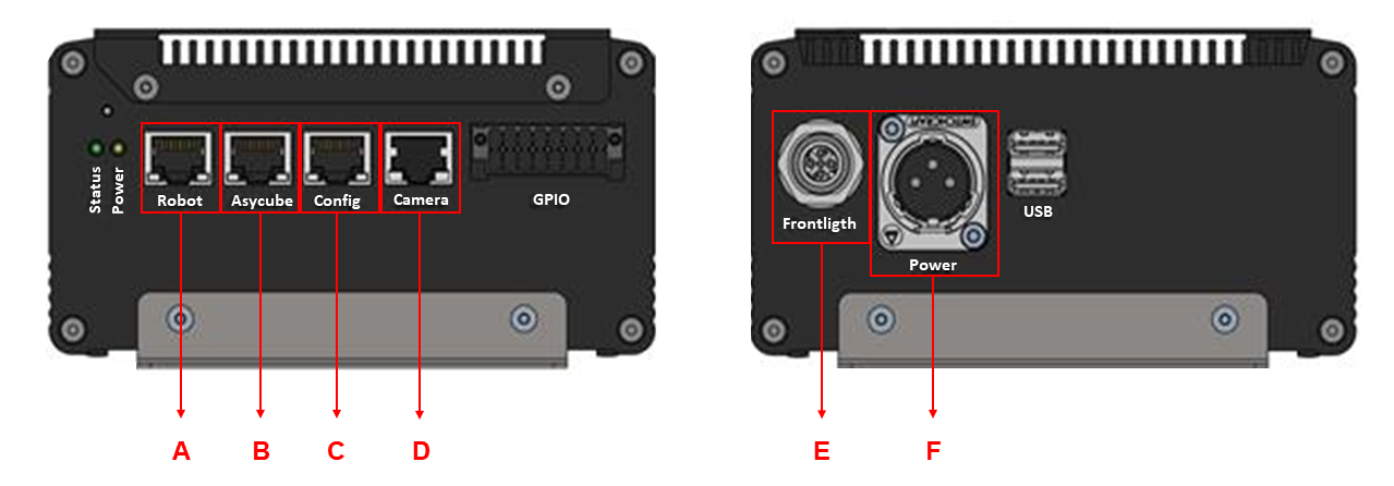
Fig. 37 EYE+ Controller connections
(A) Robot or PLC RJ45 Ethernet port
(B) Asycube RJ45 Ethernet port
(C) Configuration RJ45 Ethernet port to access EYE+ Studio from your computer or company network.
(D) Camera PoE port
(E) Frontlight connector
(F) EYE+ Controller Power connector