警告
あなたはこのドキュメントの古いバージョンを読んでいます。 最新の情報を知りたい場合は、以下を参照してください 5.4 .GPIO
GPIO cable
In the context of デュアルフィーディング, two hoppers are required. The easiest solution is to connect both hoppers to the Asycube. However, in some cases, e.g. when using the purge on an Asycube 240, it is not possible to connect two hoppers to the Asycube. For such cases, Asyril SA proposes an optional cable to connect the hoppers to the EYE+ Controller. The cable connects the GPIO connector of the EYE+ Controller on one side and the M8 cables from the hoppers on the other side.
The M8 cables from the hoppers are connected to a distribution box. This box has a 3 meters long cable ending with a female GPIO connector that is plugged to the GPIO connector on the EYE+ Controller.
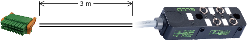
図 36 Dualfeeding cable
The distribution box has mounting holes that can be used to fasten the box:
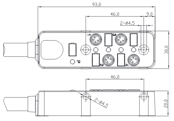
図 37 Distribution box schematic
警告
Only connect an Asyril hopper using the supplied M8 cable to the distribution box. Do not connect any other hopper or use any other cable. Failure to comply with this instruction may result in permanent damage to the EYE+ Controller or to your own device.
ピン配列
次の図は、 EYE+ Controller に搭載されているGPIOの雄コネクタのピン配列です。
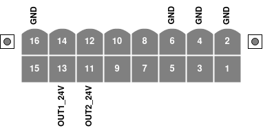
図 38 EYE+ Controller の側面から見たGPIOのオスのコネクタピン配列
ラベル付きのピンには特定の使用法があり、 EYE+ で特定の設定が必要な場合があります。現在サポートされているピンの使い方は、 表 21 に記載されています。
ピン |
指定 |
使用法 |
|---|---|---|
11 |
OUT2_24V |
ホッパー出力(例:デュアルフィーディング、 7.2 ホッパーチューニング 参照) |
13 |
OUT1_24V |
ホッパー出力(例:デュアルフィーディング、 7.2 ホッパーチューニング 参照) |
警告
The unlabeled pins (1, 3, 5, 7, 8, 9, 10, 12, 14, 15) are reserved for future use and must be left unconnected. Failure to comply with this instruction may result in permanent damage to the EYE+ Controller or to your own device.
注
GPIO メスコネクタ は EYE+ Controller に付属していないため、電子部品の販売先から別途購入する必要があります。
電源仕様
表 22 は、 EYE+ Controller のGPIOコネクタの電源仕様をまとめたものです。
ピン |
指定 |
最大電流 |
|---|---|---|
11 |
OUT2_24V |
500mA |
13 |
OUT1_24V |
500mA |
警告
表 22 に記載されている以上の電力を出力から使用しないでください。 EYE+ Controller に永久的な損傷を与える可能性があります。
メスコネクタ
GPIOコネクターは、 図 39 に記載されているように、 Phoenix Contact 社製の8ポジション16コンタクト(2列)、3.5mmピッチのメスコネクターです。
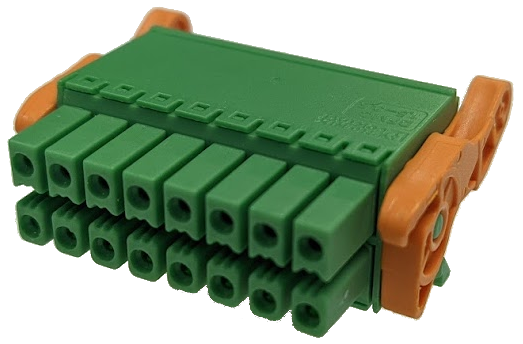
図 39 GPIO メスコネクタ
表 23 に記載されている reference 1790548 の使用を推奨します。この型式のコネクタは、レバーを使って素早く簡単にオスコネクターに固定することができます。
短い説明記事 |
PCBコネクタ |
コネクタシステム |
MINI COMBICON - DFMC 1,5 |
端子の種類 |
メスコネクタ |
記事の範囲 |
DFMC 1,5/..-ST-LR |
ピッチ |
3.5 mm |
位置の数 |
8 |
ロック式 |
ロックと解除用イジェクタレバー |
行の数 |
2 |
接続の数 |
16 |
可能性のある数 |
16 |