Warning
You are reading an old version of this documentation. If you want up-to-date information, please have a look at 5.4 .Hopper interface
Selecting the hopper
We generally recommend using the Asyfill for your flexible application. However, the choice of your hopper also depends on your complete setup.
Asyfill smart hopper
On EYE+ Studio, you will be able to configure up to 4 Asyfill in the hopper configuration.
Tip
To choose the right Asyfill for your application, discover the Asyfill range here.
The Asyfill will be connected to the EYE+ Controller using an Ethernet cable. You will need a Ethernet Switch to connect multiple Asyfill.
Other feeding devices
Using other feeding devices for multi-feeding is also possible. They can be connected through either analog or digital outputs and will be controlled by the EYE+ Controller during production.
The Asycube has two integrated digital/analog outputs. In cases where more outputs are needed (e.g. in the context of multi-feeding with three or four parts) Asyril proposes a GPIO cable to connect up to four hoppers to the GPIO connector of the EYE+ Controller. Note that the purge on an Asycube 240 also requires an Asycube output.
This table will help you select the right product for your multi-feeding application.
Asycube size |
Number of parts |
GPIO cable needed ? |
Output Type |
|---|---|---|---|
Asycube 240 |
2 |
No |
Analog or digital |
2 (with purge) |
Yes |
Digital only |
|
3 |
Yes |
Digital only |
|
4 |
Yes |
Digital only |
|
Asycube 380 |
2 |
No |
Analog or digital |
3 |
Yes |
Digital only |
|
4 |
Yes |
Digital only |
|
Asycube 530 |
2 |
No |
Analog or digital |
3 |
Yes |
Digital only |
|
4 |
Yes |
Digital only |
For more details on how to mount the hoppers around the Asycube, see the Hoppers section in the Asycube Documentation.
Connecting the hopper
Asyfill smart hopper
Asyfill must be connected to the EYE+ Controller on the Asyfill port through an Ethernet Switch.
During the hopper configuration, each hopper will have to be connected one after the other to change their IP address.
Ethernet Switch
The switch is a 10/100M, full/half-duplex, 5-port unmanaged Ethernet switch. This switch can withstand a wide temperature range (-10 to +60°C) and is specially made for the industrial environment.
Simply install it in a DIN rail and connect it to a 24V power supply (Input Current : 0.11 A @ 24 VDC) using the removable 3-contact terminal block.
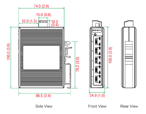
Fig. 293 Switch dimensions - Unit: mm (inch)
Note
It is not mandatory to use the switch provided by Asyril, but this switch model has been tested and validated to work properly with EYE+ for any of your applications.
Other feeding devices
Analog hoppers must be connected directly to the analog outputs of your Asycube.
Digital hoppers such as Asyril standard hopper can either be connected to the digital outputs of the Asycube or to the EYE+ Controller using a GPIO cable (see Other feeding devices - Available outputs depending on the number of parts).
GPIO cable
The cable connects the GPIO connector of the EYE+ Controller on one side and the M8 cables from the hoppers on the other side.
The M8 cables from the hoppers are connected to a distribution box. This box has a 3 meters long cable ending with an 8-position female GPIO connector with 16 contacts (2 rows), 3.5 mm pitch, that is plugged to the GPIO connector on the EYE+ Controller.
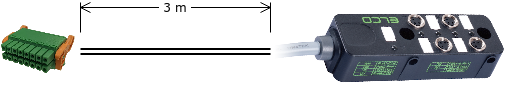
Fig. 294 Multi-feeding cable
The distribution box has mounting holes that can be used to fasten the box:
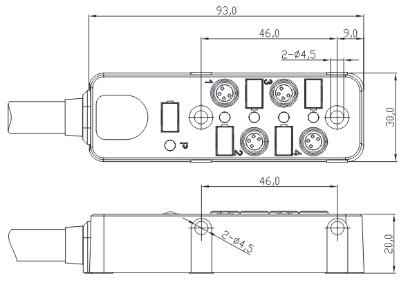
Fig. 295 Distribution box schematic
Important
Only connect an Asyril standard hopper using the supplied M8 cable to the distribution box. Do not connect any other hopper or use any other cable. Failure to comply with this instruction may result in permanent damage to the EYE+ Controller or to your own device.