Warning
You are reading an old version of this documentation. If you want up-to-date information, please have a look at 5.4 .Electrical interfaces
The EYE+ Controller must be connected to :
Power supply
Asycube
Camera
Furthermore, several other interfaces are available to connect:
Robot or PLC for production
Computer or company network for configuration
Frontlight
Hopper(s) (Asyfill smart hopper, standard hopper or other feeding devices)
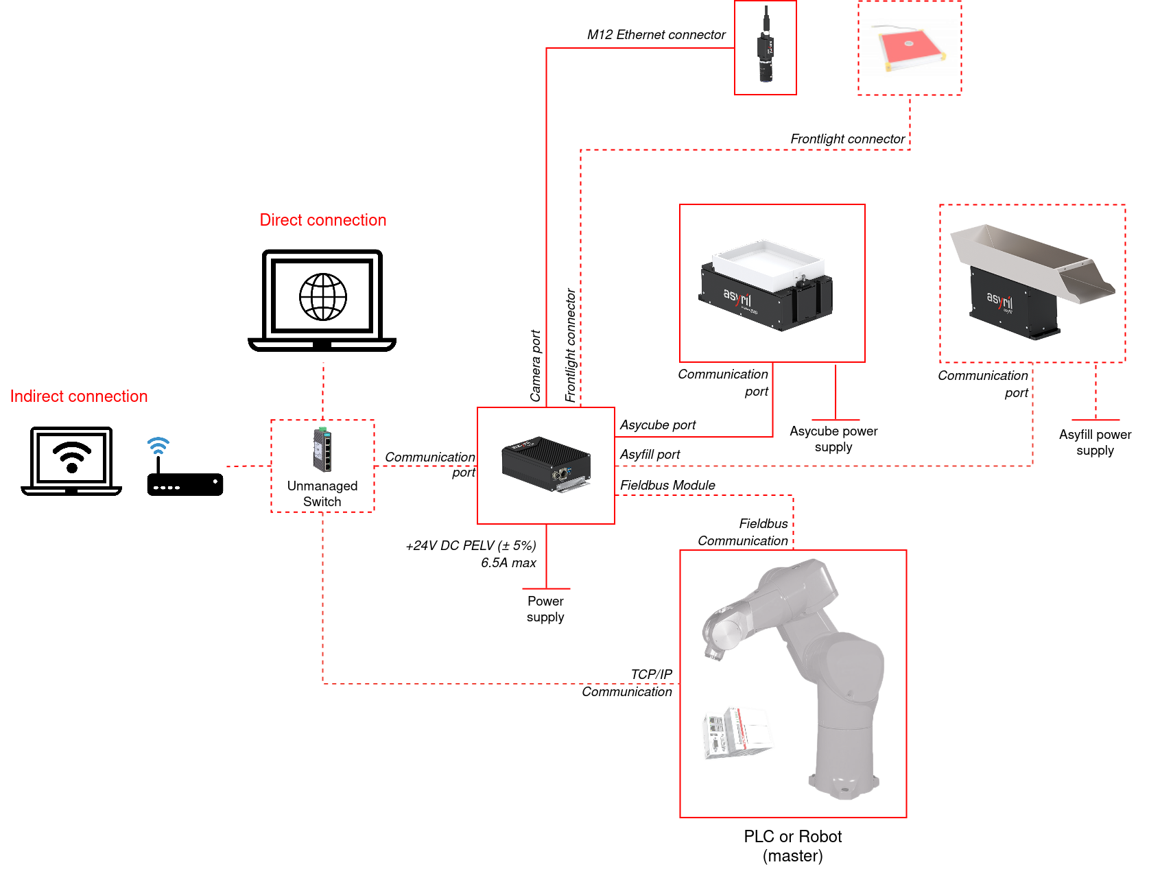
Fig. 46 EYE+ overall wiring diagram (cover rev. 1)
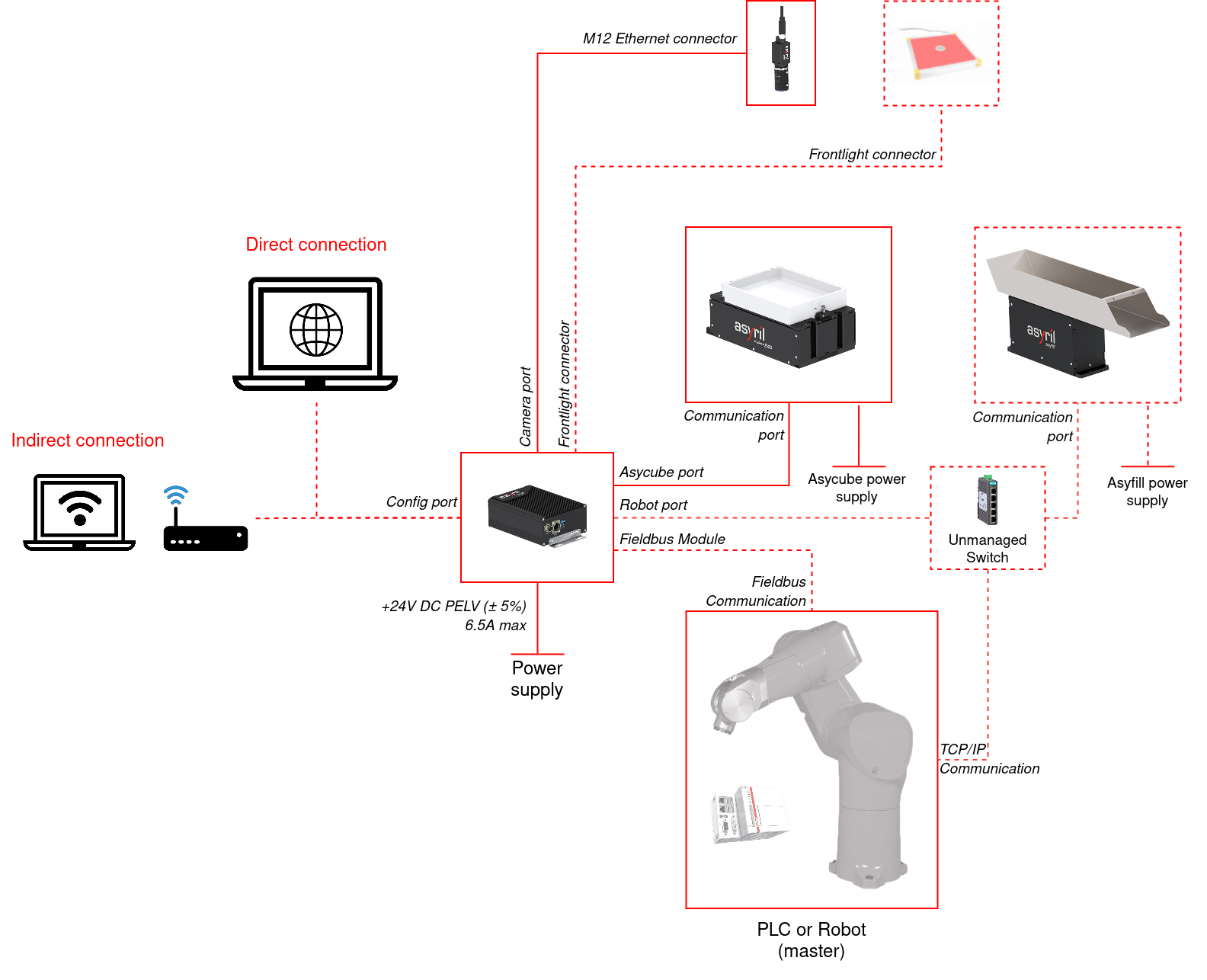
Fig. 47 EYE+ overall wiring diagram (cover rev. 0)
Note
Communication cables can be ordered in different lengths depending on your needs.
Connector Overview
The EYE+ Controller has connectors on both sides to connect the devices mentioned above.
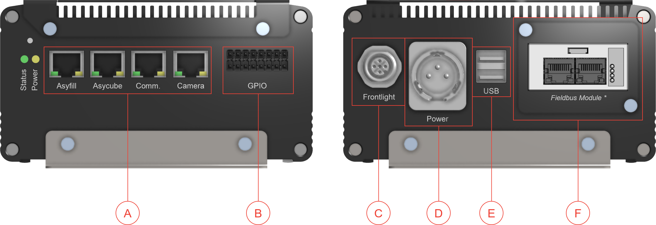
Fig. 48 EYE+ Controller connections (cover rev. 1)

Fig. 49 EYE+ Controller connections (cover rev. 0)
(A) Ethernet Connections RJ45 Ethernet ports
(B) GPIO connector
(C) Frontlight connector
(D) Power supply connector
(E) USB connectors, used for System backup and System restore
(F) Optional Fieldbus Module