Warning
You are reading an old version of this documentation. If you want up-to-date information, please have a look at 5.4 .Frontlight
While it is optional, for some applications a frontlight might be required. This is typically the case when the upper surface of the part must be observed in order to correctly identify pickable parts.
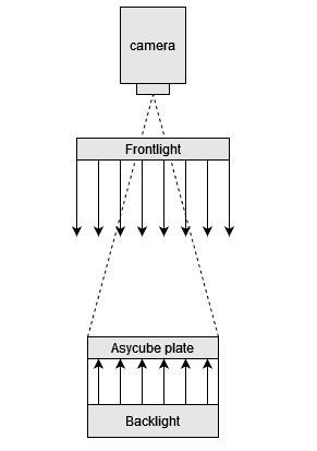
Fig. 35 Types of available lighting
Note
Refer to section Effect of each type of lighting for more information.
The type of frontlight depends on the size of your Asycube.
Asycube model |
Frontlight type |
|---|---|
Asycube 50 |
|
Asycube 80 |
|
Asycube 240 |
|
Asycube 380 |
|
Asycube 530 |
Note
CAD models are included in the EYE+ kit CAD files available for download.
DOAL (Asycube 50/80)
Dimensions
DOAL 100 |
||
|---|---|---|
A |
123.8 |
|
B |
120 |
|
C |
168.7 |
|
D |
18.2 |
|
E |
100 |
|
F |
100 |
|
G, H |
50 |
|
Holes |
M5 x 6 |
|
VDC [V] |
24 |
|
I [mA] |
570 | 945 |
|
Color |
R |
G, B, W |
Weight |
1.2 kg |
|
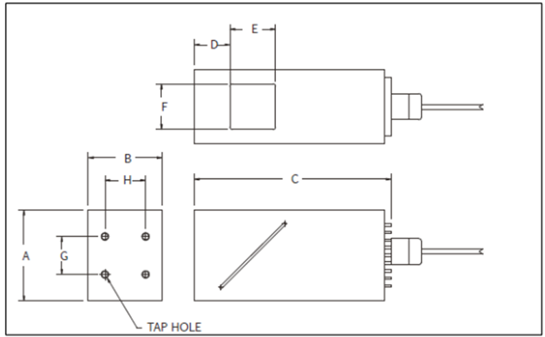
Fig. 36 DOAL dimensions
Mounting the frontlight
The frontlight must be mounted centrally with respect to the Asycube plate using the four M5 tap holes. The camera should be mounted centrally as well, with the tip of the lens 5-10mm above the frontlight.
Flat dome (Asycube 240/380)
Dimensions
Flat dome 400x300 |
Flat dome 500x400 |
|
|---|---|---|
A |
43.2 |
43.2 |
B |
340 |
440 |
C |
440 |
540 |
D |
Ø40 |
Ø50 |
E |
35 |
35 |
F |
25 |
25 |
G, H |
45 |
45 |
Holes |
M6 x 5 |
M6 x 5 |
VDC [V] |
24 |
24 |
I [mA] |
3500 |
3500 |
Color |
R, G, B, W, IR |
R, W |
Weight |
4.3 kg |
7 kg |
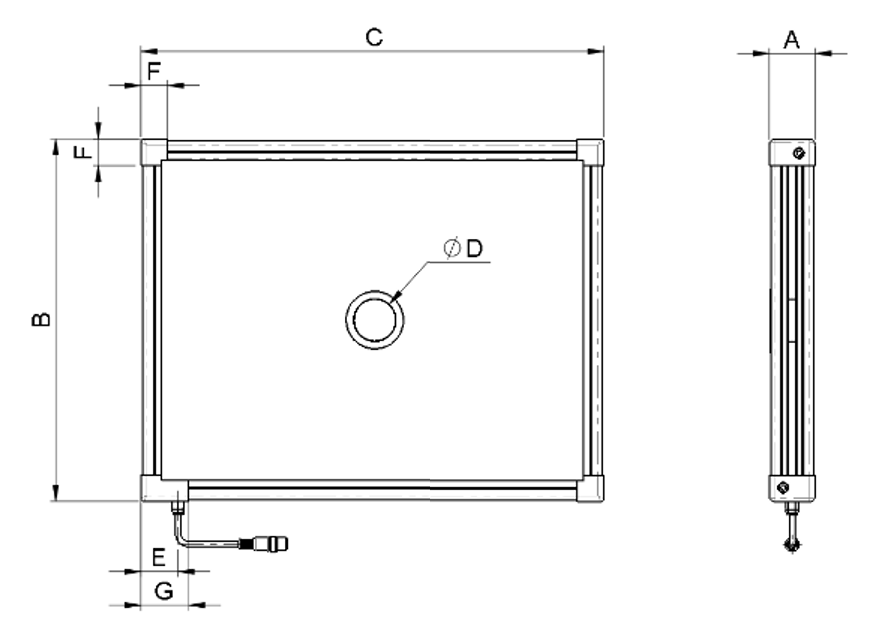
Fig. 37 Flat dome dimensions
Mounting the frontlight
The flat dome is supplied with six M6 bolts which can be inserted freely in the nuts around the whole circumference (on each side). The frontlight must be mounted centrally with respect to the Asycube plate. The camera should be mounted centrally as well, with the tip of the lens 5-10mm above the frontlight.
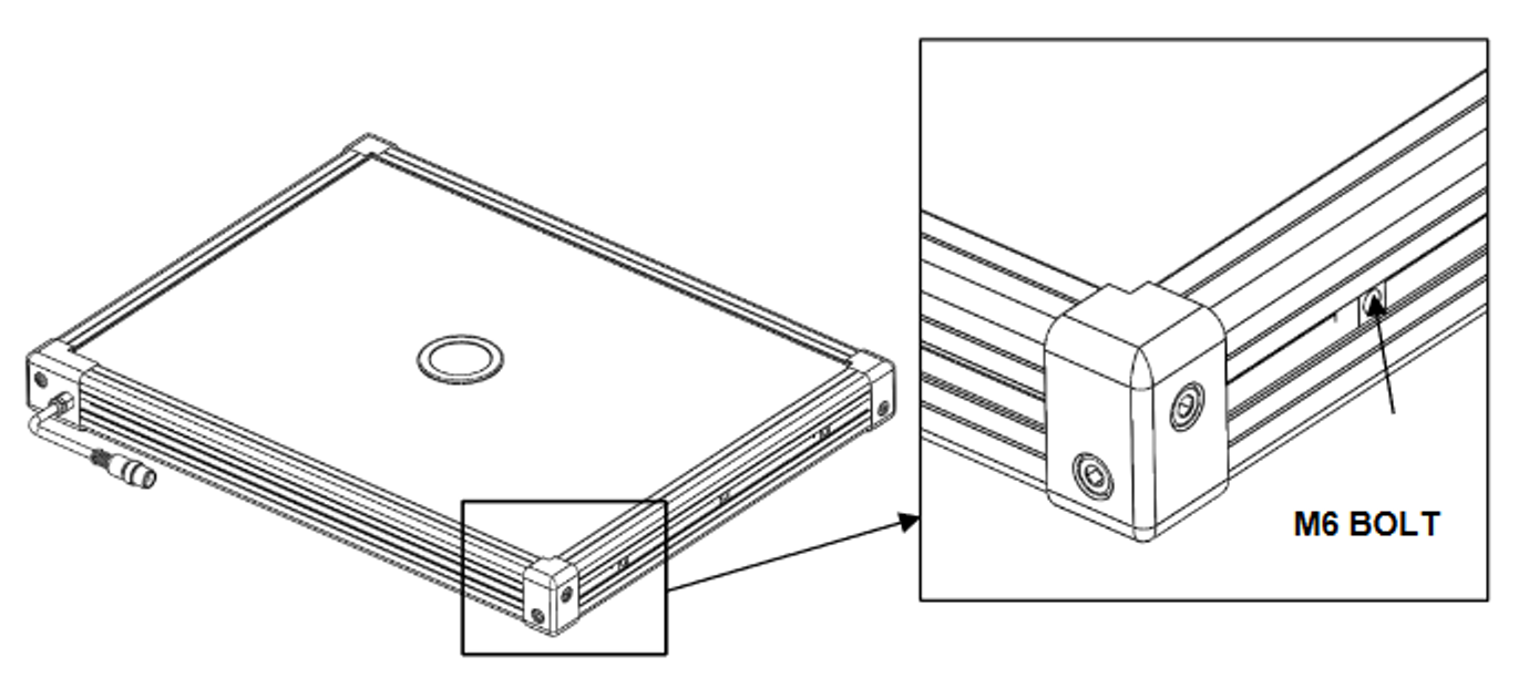
Fig. 38 Flat dome mounting holes
To mount the camera support, you can use the four M4 holes placed around the camera opening.
Important
The length of the screws used to secure the camera mounting should not penetrate more than 4.5mm within the M4 thread. Using screws that are too long can damage to your frontlight and EYE+ Controller.
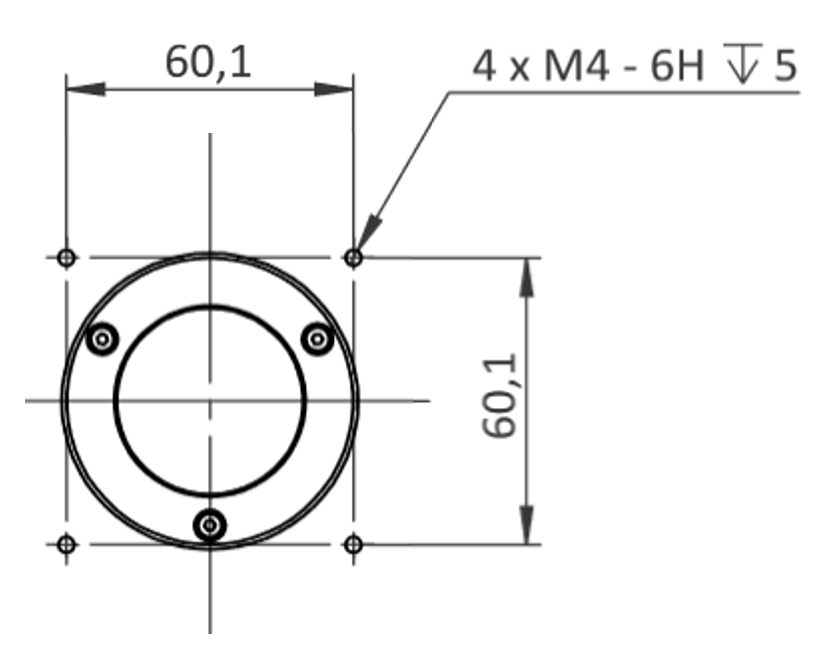
Fig. 39 Flat dome camera support mounting holes
Bars lighting (Asycube 530)
Dimensions
Bars lighting |
|
|---|---|
VDC [V] |
24 |
I [mA] |
3200 |
Color |
R |
Weight |
6.5 kg |
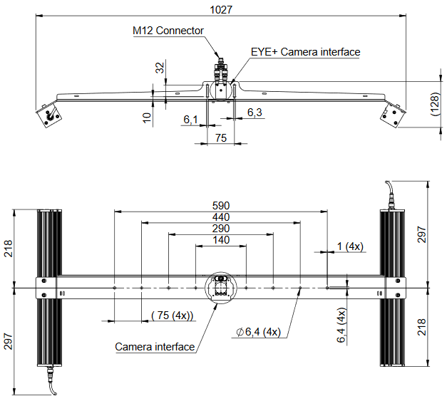
Fig. 40 Bar light dimensions
Mounting the frontlight
The bar lighting is supplied with a mounting bracket to fix the camera, the cables and the M12 connector.